Toyota Sienna Service Manual: Seat Belt Buckle Switch LH Circuit Malfunction
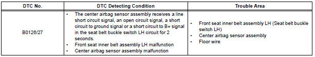
DTC B0126/27 Seat Belt Buckle Switch LH Circuit Malfunction
DESCRIPTION
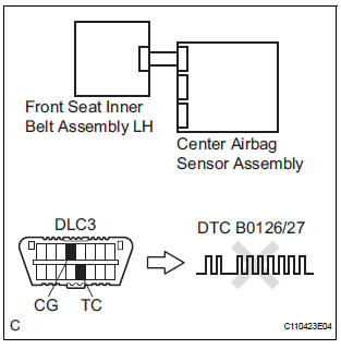
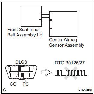
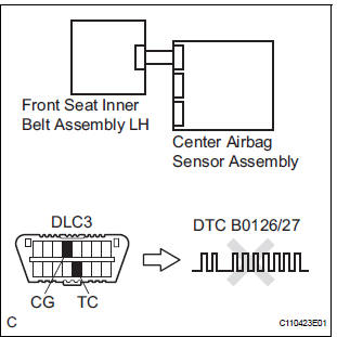
The seat belt buckle switch LH circuit consists of the center airbag sensor assembly and the front seat inner belt assembly LH.
DTC B0126/27 is recorded when a malfunction is detected in the seat belt buckle switch LH circuit
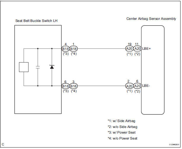
WIRING DIAGRAM
INSPECTION PROCEDURE
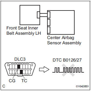
1 CHECK DTC
- Turn the ignition switch to the ON position, and wait for at least 60 seconds.
- Clear the DTCs stored in memory.
- Turn the ignition switch to the LOCK position.
- Turn the ignition switch to the ON position, and wait for at least 60 seconds.
- Check the DTCs.
OK: DTC B0126/27 is not output.
HINT: Codes other than code B0126/27 may be output at this time, but they are not related to this check.
USE SIMULATION METHOD TO CHECK
2 CHECK CONNECTION OF CONNECTORS
- Turn the ignition switch to the LOCK position.
- Disconnect the negative (-) terminal cable from the battery, and wait for at least 90 seconds.
- Check that the connectors are properly connected to the center airbag sensor assembly and the front seat inner belt assembly LH.
OK: The connectors are connected.
3 CHECK VEHICLE
- Check the front driver seat type.
Result

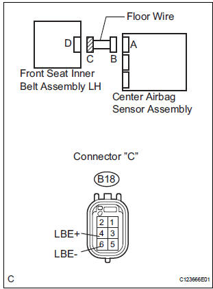
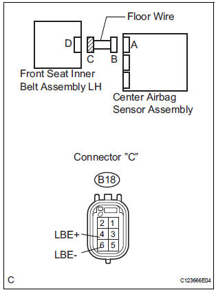
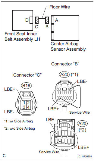
4 CHECK FLOOR WIRE (OPEN)
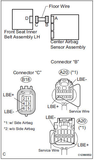
- Disconnect the connectors from the center airbag sensor assembly and the front seat inner belt assembly LH.
- w/ Side airbag: Using a service wire, connect A20-19 (LBE+) and A20-2 (LBE-) of connector "B".
NOTICE: Do not forcibly insert a service wire into the terminals of the connector when connecting.
- w/o Side airbag: Using a service wire, connect A20-11 (LBE+) and A20-6 (LBE-) of connector "B".
NOTICE: Do not forcibly insert a service wire into the terminals of the connector when connecting.
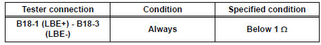
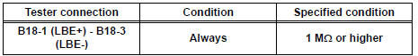
- Measure the resistance according to the value(s) in the table below.
Standard resistance
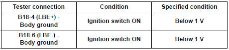
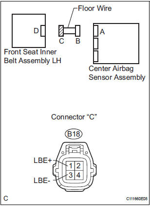
5 CHECK FLOOR WIRE (SHORT TO B+)
- Disconnect the service wire from connector "B".
- Connect the negative (-) terminal cable to the battery, and wait for at least 2 seconds.
- Turn the ignition switch to the ON position.
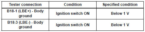
- Measure the voltage according to the value(s) in the table below.
Standard voltage
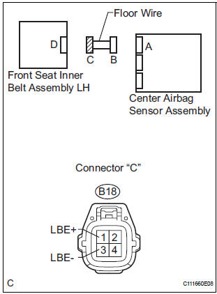
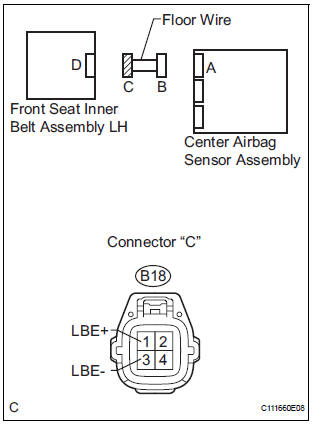
6 CHECK FLOOR WIRE (SHORT TO GROUND)
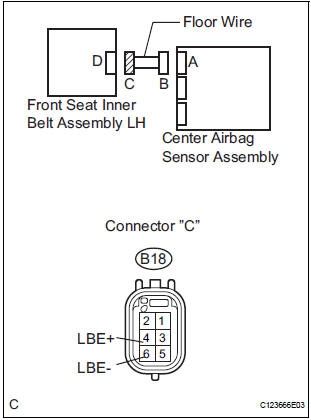
- Turn the ignition switch to the LOCK position.
- Disconnect the negative (-) terminal cable from the battery, and wait for at least 90 seconds.
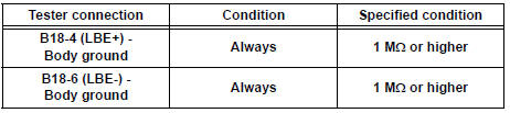
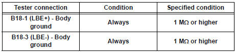
- Measure the resistance according to the value(s) in the table below.
Standard resistance
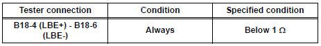
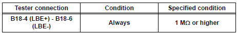
7 CHECK FLOOR WIRE (SHORT)
- Measure the voltage according to the value(s) in the table below.
Standard resistance
8 CHECK FRONT SEAT INNER BELT ASSEMBLY LH
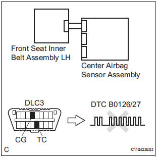
- Connect the connectors to the front seat inner belt assembly LH and the center airbag sensor assembly.
- Connect the negative (-) terminal cable to the battery, and wait for at least 2 seconds.
- Turn the ignition switch to the ON position, and wait for at least 60 seconds.
- Clear the DTCs stored in memory.
- Turn the ignition switch to the LOCK position.
- Turn the ignition switch to the ON position, and wait for at least 60 seconds.
- Check the DTCs.
OK: DTC B0126/27 is not output.
HINT: Codes other than code B0126/27 may be output at this time, but they are not related to this check.
USE SIMULATION METHOD TO CHECK
9 REPLACE FRONT SEAT INNER BELT ASSEMBLY LH
- Turn the ignition switch to the LOCK position.
- Disconnect the negative (-) terminal cable from the battery, and wait for at least 90 seconds.
- Replace the front seat inner belt assembly LH.
HINT: Perform the inspection using parts from a normal vehicle if possible.
10 CHECK CENTER AIRBAG SENSOR ASSEMBLY
- Connect the negative (-) terminal cable to the battery, and wait for at least 2 seconds.
- Turn the ignition switch to the ON position, and wait for at least 60 seconds.
- Clear the DTCs stored in memory.
- Turn the ignition switch to the LOCK position.
- Turn the ignition switch to the ON position, and wait for at least 60 seconds.
- Check the DTCs.
OK: DTC B0126/27 is output.
HINT: Codes other than code B0126/27 may be output at this time, but they are not related to this check.
END
11 CHECK FLOOR WIRE (OPEN)
- Disconnect the connectors from the center airbag sensor assembly and the front seat inner belt assembly LH.
- w/ Side airbag:
Using a service wire, connect A20-19 (LBE+) and A20-2
(LBE-) of connector "B".
NOTICE: Do not forcibly insert a service wire into the terminals of the connector when connecting.
- w/o Side airbag:
Using a service wire, connect A20-11 (LBE+) and A20-6
(LBE-) of connector "B".
NOTICE: Do not forcibly insert a service wire into the terminals of the connector when connecting.
- Measure the resistance according to the value(s) in the table below.
Standard resistance
12 CHECK FLOOR WIRE (SHORT TO B+)
- Disconnect the service wire from connector "B".
- Connect the negative (-) terminal cable to the battery, and wait for at least 2 seconds.
- Turn the ignition switch to the ON position.
- Measure the voltage according to the value(s) in the table below.
Standard voltage
13 CHECK FLOOR WIRE (SHORT TO GROUND)
- Turn the ignition switch to the LOCK position.
- Disconnect the negative (-) terminal cable from the battery, and wait for at least 90 seconds.
- Measure the resistance according to the value(s) in the table below.
Standard resistance
14 CHECK FLOOR WIRE (SHORT)
- Measure the resistance according to the value(s) in the table below.
Standard resistance
15 CHECK FRONT SEAT INNER BELT ASSEMBLY LH
- Connect the connectors to the front seat inner belt assembly LH and the center airbag sensor assembly.
- Connect the negative (-) terminal cable to the battery, and wait for at least 2 seconds.
- Turn the ignition switch to the ON position, and wait for at least 60 seconds.
- Clear the DTCs stored in memory.
- Turn the ignition switch to the LOCK position.
- Turn the ignition switch to the ON position, and wait for at least 60 seconds.
- Check the DTCs.
OK: DTC B0126/27 is not output.
HINT: Codes other than code B0126/27 may be output at this time, but they are not related to this check.
USE SIMULATION METHOD TO CHECK
16 REPLACE FRONT SEAT INNER BELT ASSEMBLY LH
- Turn the ignition switch to the LOCK position.
- Disconnect the negative (-) terminal cable from the battery, and wait for at least 90 seconds.
- Replace the front seat inner belt assembly LH.
HINT: Perform the inspection using parts from a normal vehicle if possible.
17 CHECK CENTER AIRBAG SENSOR ASSEMBLY
- Connect the negative (-) terminal cable to the battery, and wait for at least 2 seconds.
- Turn the ignition switch to the ON position, and wait for at least 60 seconds.
- Clear the DTCs stored in memory.
- Turn the ignition switch to the LOCK position.
- Turn the ignition switch to the ON position, and wait for at least 60 seconds.
- Check the DTCs.
OK: DTC B0126/27 is not output.
HINT: Codes other than code B0126/27 may be output at this time, but they are not related to this check.
END
 Short to B+ in Side Squib LH Circuit
DTC B0118/46 Short to B+ in Side Squib LH Circuit
DESCRIPTION
The side squib LH circuit consists of the center airbag sensor assembly and
the front seat side airbag
assembly LH (side squib LH).
...
 Short in Front Pretensioner Squib RH Circuit
DTC B0130/63 Short in Front Pretensioner Squib RH Circuit
DESCRIPTION
The front pretensioner squib RH circuit consists of the center airbag sensor
assembly and the front seat
outer belt assembly ...
Other materials:
System description
1. SYSTEM DESCRIPTION
(a) ABS
(Anti-lock Brake System)
The ABS helps prevent wheels from locking when
the brake is applied firmly or when braking on a
slippery surface.
(b) EBD
(Electronic Brake force Distribution)
The EBD control utilizes ABS, realizing proper
brake force distribution betw ...
Data list / active test
HINT:
By accessing the DATA LIST displayed by the intelligent
tester, you can perform such functions as reading the values
of switches and sensors without removing any parts. Reading
the DATA LIST as the first step in troubleshooting is one
method to shorten labor time.
1. DATA LIST FOR OCCUPA ...
Sliding doors
Vehicles without power sliding doors
The sliding doors can be opened and closed using the sliding
door handle. The sliding door can be locked and unlocked using
the wireless remote control, door lock switch or inside lock
knob.
Vehicles with power sliding doors
...
