
Toyota Sienna Service Manual: Second brake piston
COMPONENTS
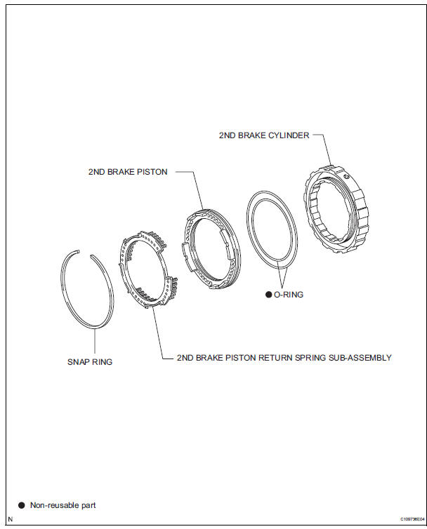
 Reassembly
1. INSTALL FRONT OIL PUMP OIL SEAL
(a) Using SST and a hammer, install a new oil seal to
the oil pump body.
SST 09350-32014 (09351-32140)
HINT:
The seal end should be flat with the outer edge ...
 Disassembly
1. REMOVE 2ND BRAKE PISTON RETURN SPRING
SUB-ASSEMBLY
(a) Place SST on the return spring and compress the
return spring with a press.
SST 09387-00060
(b) Using a screwdriver, remove the snap ...
Other materials:
Fuel Pump Primary Circuit
DESCRIPTION
This DTC is designed to detect a malfunction in the fuel pump (FUEL
PUMP) relay circuit. When the
system is normal, the battery voltage is applied to FPR terminal of the ECM
while the FUEL PUMP
relay is turned OFF. If the battery voltage is not applied to the FPR
ter ...
Oil and oil filter
COMPONENTS
REPLACEMENT
CAUTION:
Prolonged and repeated contact with engine oil will
result in the removal of natural oils from the skin,
leading to dryness, irritation and dermatitis. In
addition, used engine oil contains potentially harmful
contaminants which may caus ...
Removal
1. DISCONNECT CABLE FROM NEGATIVE BATTERY
TERMINAL
2. REMOVE FRONT DOOR SCUFF PLATE LH
3. REMOVE COWL SIDE TRIM SUB-ASSEMBLY LH
4. REMOVE LOWER INSTRUMENT PANEL FINISH
PANEL SUB-ASSEMBLY LH (See page IP-6)
5. REMOVE TIRE PRESSURE WARNING RESET SWITCH
(a) Disengage the 2 claws and remove t ...
