Toyota Sienna Service Manual: SFR Solenoid Circuit
DESCRIPTION
This solenoid goes on when signals are received from the ECU and controls the pressure acting on the wheel cylinders to control the braking force.
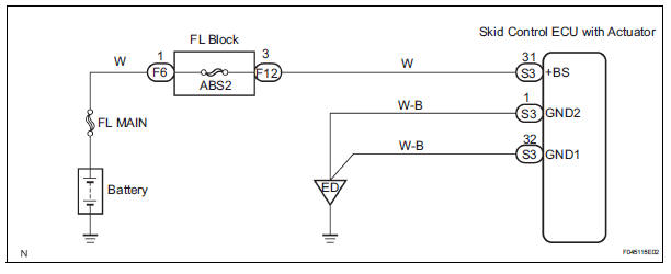
WIRING DIAGRAM
INSPECTION PROCEDURE
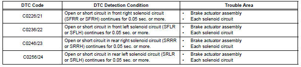
1 RECONFIRM DTC
HINT: This code is detected when a problem is determined in the brake actuator assembly.
The solenoid circuit is in the brake actuator assembly.
Therefore, solenoid circuit inspection and solenoid unit inspection cannot be performed. Be sure to check if the DTC code is output before replacing the brake actuator assembly.
(a) Clear the DTCs (See page BC-82).
(b) Turn the ignition switch to the ON position.
(c) Are the same DTCs recorded?
Result 
NOTICE: When replacing the brake actuator assembly, perform zero point calibration (See page BC-70).

REPLACE BRAKE ACTUATOR ASSEMBLY
 Right Rear Wheel Speed Sensor Signal
DESCRIPTION
Refer to DTCs C0200/31, C0205/32, C1235/35 and C1236/36 (See page BC-92).
HINT:
DTC C0210/33 and C1238/38 are for the right rear speed sensor.
DTC C0215/34 and C1239/39 are ...
 Open or Short Circuit in ABS Motor Relay Circuit
DESCRIPTION
The ABS motor relay supplies power to the ABS pump motor. While the ABS &
TRAC & VSC are
activated, the ECU switches the ABS motor relay ON and operates the ABS pump
moto ...
Other materials:
Oxygen (A/F) Sensor Pumping Current Circuit
HINT:
Although the DTC titles say oxygen sensor, these DTCs relate to the
Air-Fuel Ratio (A/F) sensor.
Sensor 1 refers to the sensor mounted in front of the Three-Way
Catalytic Converter (TWC) and
located near the engine assembly.
DESCRIPTION
Refer to DTC P2195 (See page ES-355 ...
Crankshaft position sensor
Components
Removal
1. Remove compressor and magnetic clutch
HINT:
(See page AC-227 )
2. REMOVE CRANKSHAFT POSITION SENSOR
(a) Disconnect the crankshaft position sensor
connector.
(b) Remove the bolt, and then remove the crankshaft
position sensor.
INSPECTION
1. INSPECT CRANKSHAFT ...
When servicing full-time 4wd vehicles
The full-time 4WD SIENNA is equipped with the open
center differential system.
If incorrect preparations or test procedures are used, the
test will not only be unsuccessful, but may be dangerous
as well.
Therefore, before beginning any such servicing or test,
be sure to check the following ...
