Toyota Sienna 2010-2026 Owners Manual: Shifting the shift lever
 While the engine switch is in the
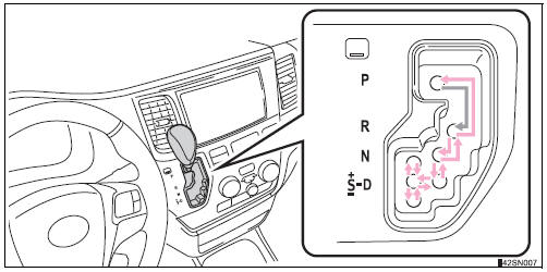
“ON” position (vehicles without a
smart key system) or IGNITION ON mode (vehicles with a smart
key system), move the shift lever with the brake pedal
depressed.
When shifting the shift lever between P and D, make sure that the vehicle is completely stopped.

 Shift position purpose
*1: Shifting to the D position allows the system to select a gear suitable
for
the driving conditions. Setting the shift lever to the D position is recommended
for normal driving.
*2: Selec ...
Other materials:
Terminals of ECU
1. CENTER AIRBAG SENSOR ASSEMBLY (w/ Side
Airbag)
2. CENTER AIRBAG SENSOR ASSEMBLY (w/o Side
Airbag)
...
Power Seat Motor Circuit
DESCRIPTION
When the power seat control switch is operated, a command signal is sent to
the position control ECU
and switch assembly (power seat control switch and ECU). The front power seat
switch then controls the
appropriate seat motor as needed. This memory system does not use a seat
po ...
Precaution
1. PRECAUTION
(a) Before inspecting and repairing the fuel system,
disconnect the cable from the negative (-) battery
terminal.
(b) Do not smoke or work near fire when handling the
fuel system.
(c) Keep gasoline away from rubber or leather parts.
2. DISCHARGE FUEL SYSTEM PRESSURE (*1)
...
