Toyota Sienna Service Manual: Short in Driver Side Squib 2nd Step Circuit
DTC B1180/17 Short in Driver Side Squib 2nd Step Circuit
DESCRIPTION
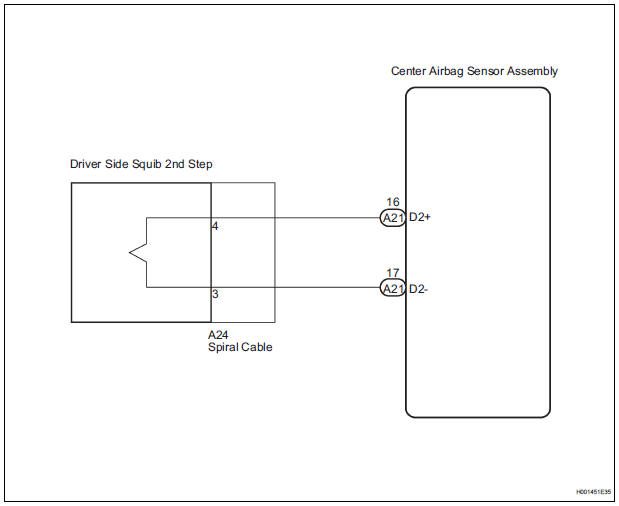
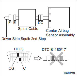
The driver side squib 2nd step circuit consists of the center airbag sensor assembly, the spiral cable and the steering pad.
The circuit instructs the SRS to deploy when deployment conditions are met.
DTC B1180/17 is recorded when a short circuit is detected in the driver side squib 2nd step circuit.
|
DTC No. |
DTC Detecting Condition |
Trouble Area |
|
B1180/17 |
|
|
WIRING DIAGRAM
INSPECTION PROCEDURE
HINT:
- Perform the simulation method by selecting the "check mode" (signal check) with the intelligent tester
- After selecting the "check mode" (signal check), perform the simulation method by wiggling each connector of the airbag system or driving the vehicle on a city or rough road
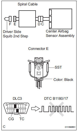
1 CHECK STEERING PAD (DRIVER SIDE SQUIB 2ND STEP)
- Turn the ignition switch to the LOCK position.
- Disconnect the negative (-) terminal cable from the battery, and wait for at least 90 seconds.
- Disconnect the connectors from the steering pad.
- Connect the white wire side of SST (resistance 2.1 Ω) to the spiral cable.
CAUTION: Never connect a tester to the steering pad (driver side squib 2nd step) for measurement, as this may lead to a serious injury due to airbag deployment.
NOTICE: Do not forcibly insert the SST into the terminals of the connector when connecting.
Insert the SST straight into the terminals of the connector.
SST 09843-18060
- Connect the negative (-) terminal cable to the battery, and wait for at least 2 seconds.
- Turn the ignition switch to the ON position, and wait for at least 60 seconds.
- Clear the DTCs stored in memory (5).
- Turn the ignition switch to the LOCK position.
- Turn the ignition switch to the ON position, and wait for at least 60 seconds.
- Check the DTCs (5).
OK: DTC B1180/17 is not output. HINT: Codes other than DTC B1180/17 may be output at this time, but they are not related to this check.
 Go to step 2

REPLACE STEERING PAD
2 CHECK CONNECTORS
- Turn the ignition switch to the LOCK position.
- Disconnect the negative (-) terminal cable from the battery, and wait for at least 90 seconds.
- Disconnect the SST (resistance 2.1 Ω) from the spiral cable.
- Check that the spiral cable connectors (on the steering pad side) are not damaged.
OK: The lock button is not disengaged, and the claw of the lock is not deformed or damaged.
 REPLACE SPIRAL CABLE

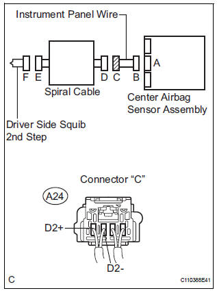
3 CHECK DRIVER SIDE SQUIB 2ND STEP CIRCUIT
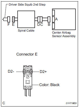
- Disconnect the connector from the center airbag sensor assembly.
- Release the activation prevention mechanism built into connector "B" (7).
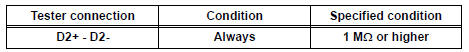
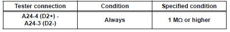
- Measure the resistance according to the value(s) in the table below.
Standard resistance
 Go to step 5

4 CHECK CENTER AIRBAG SENSOR ASSEMBLY
- Connect the connectors to the steering pad and the center airbag sensor assembly.
- Connect the negative (-) terminal cable to the battery, and wait for at least 2 seconds.
- Turn the ignition switch to the ON position, and wait for at least 60 seconds.
- Clear the DTCs stored in memory (5).
- Turn the ignition switch to the LOCK position.
- Turn the ignition switch to the ON position, and wait for at least 60 seconds.
- Check the DTCs (5).
OK: DTC B1180/17 is not output.
HINT: Codes other than DTC B1180/17 may be output at this time, but they are not related to this check.
 REPLACE CENTER AIRBAG SENSOR
ASSEMBLY
REPLACE CENTER AIRBAG SENSOR
ASSEMBLY

USE SIMULATION METHOD TO CHECK
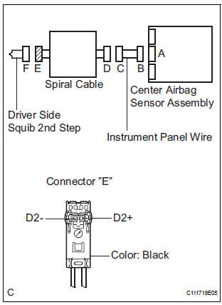
5 CHECK INSTRUMENT PANEL WIRE
- Disconnect the instrument panel wire connector from the
spiral cable.
HINT: The activation prevention mechanism of connector "B" has already been released.
- Measure the resistance according to the value(s) in the table below.
Standard resistance
 REPAIR OR REPLACE INSTRUMENT
PANEL
WIRE
REPAIR OR REPLACE INSTRUMENT
PANEL
WIRE

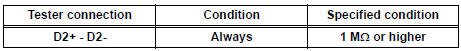
6 CHECK SPIRAL CABLE
- Release the activation prevention mechanism built into connector "D" (7).
- Measure the resistance according to the value(s) in the table below.
Standard resistance
 REPLACE SPIRAL CABLE

USE SIMULATION METHOD TO CHECK
 Short to B+ in Curtain Shield Squib LH Circuit
DTC B1168/86 Short to B+ in Curtain Shield Squib LH Circuit
DESCRIPTION
The curtain shield squib LH circuit consists of the center airbag sensor
assembly and the curtain shield
airbag assembly LH ...
 Open in Driver Side Squib 2nd Step Circuit
DTC B1181/18 Open in Driver Side Squib 2nd Step Circuit
DESCRIPTION
The driver side squib 2nd step circuit consists of the center airbag sensor
assembly, the spiral cable and
the steering pad.
...
Other materials:
Installation
1. INSTALL REAR AXLE HUB & BEARING ASSEMBLY LH
(a) Install the hub & Bearing assembly LH with the 4
bolts.
Torque: 56 N*m (571 kgf*cm, 41 ft.*lbf)
2. INSPECT BEARING BACKLASH (See page AH-16)
3. INSPECT AXLE HUB DEVIATION (See page AH-16)
4. CONNECT SKID CONTROL SENSOR WIRE
(a) Co ...
Inspection
1. INSPECT INVERTER MAIN SWITCH
Inspect the continuity between terminal at the each
switch position shown in the chart.
If continuity is not as specified, replace the main
switch assembly.
Inspect the bulb state when connecting the battery
to each terminal
...
Poor Sound Quality in All Modes (Low Volume)
INSPECTION PROCEDURE
1 CHECK AUDIO SETTINGS
Set "BASS", "MID", and "TREB" to the initial values and
check that sound is normal.
OK:
Malfunction disappears.
2 COMPARE WITH ANOTHER VEHICLE OF SAME MODEL
Compare with another vehicle of the same model.
...
