Toyota Sienna Service Manual: Short in Side Squib RH Circuit
DTC B0110/43 Short in Side Squib RH Circuit
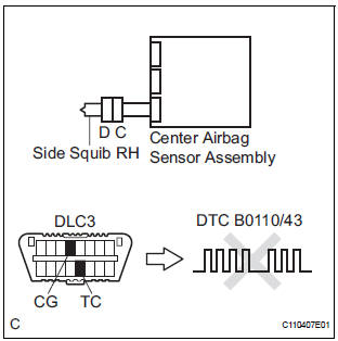
DESCRIPTION
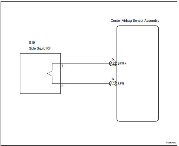
The side squib RH circuit consists of the center airbag sensor assembly and the front seat side airbag assembly RH.
The circuit instructs the SRS to deploy when deployment conditions are met.
DTC B0110/43 is recorded when a short circuit is detected in the side squib RH circuit.
|
DTC No. |
DTC Detecting Condition |
Trouble Area |
|
B0110/43 |
|
|
WIRING DIAGRAM
INSPECTION PROCEDURE
HINT:
- Perform the simulation method by selecting the "check mode" (signal check) with the intelligent tester
- After selecting the "check mode" (signal check), perform the simulation method by wiggling each connector of the airbag system or driving the vehicle on a city or rough road
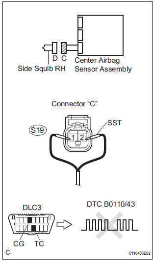
1 CHECK FRONT SEAT SIDE AIRBAG ASSEMBLY RH (SIDE SQUIB RH)
- Turn the ignition switch to the LOCK position.
- Disconnect the negative (-) terminal cable from the battery, and wait for at least 90 seconds.
- Disconnect the connectors from the front seat side airbag assembly RH.
- Connect the black wire side of SST (resistance 2.1 Ω) to the floor wire No. 2.
CAUTION: Never connect a tester to the front seat side airbag assembly RH (side squib RH) for measurement, as this may lead to a serious injury due to airbag deployment.
NOTICE: Do not forcibly insert the SST into the terminals of the connector when connecting.
Insert the SST straight into the terminals of the connector.
SST 09843-18060
- Connect the negative (-) terminal cable to the battery, and wait for at least 2 seconds.
- Turn the ignition switch to the ON position, and wait for at least 60 seconds.
- Clear the DTCs stored in memory (5).
- Turn the ignition switch to the LOCK position.
- Turn the ignition switch to the ON position, and wait for at least 60 seconds.
- Check the DTCs (5).
OK: DTC B0110/43 is not output. HINT: Codes other than DTC B0110/43 may be output at this time, but they are not related to this check.
 Go to step 2

REPLACE FRONT SEAT ASSEMBLY RH
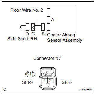
2 CHECK FLOOR WIRE NO.2 (SIDE SQUIB RH CIRCUIT)
- Turn the ignition switch to the LOCK position.
- Disconnect the negative (-) terminal cable from the battery, and wait for at least 90 seconds.
- Disconnect the SST (resistance 2.1 Ω) from the floor wire No. 2.
- Disconnect the connector from the center airbag sensor assembly.
- Release the activation prevention mechanism built into connector "B" (7).
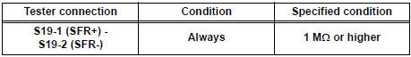
- Measure the resistance according to the value(s) in the table below.
Standard resistance
 REPAIR OR REPLACE FLOOR WIRE
NO.2
REPAIR OR REPLACE FLOOR WIRE
NO.2

3 CHECK CENTER AIRBAG SENSOR ASSEMBLY
- Connect the connectors to the front seat side airbag assembly RH and the center airbag sensor assembly.
- Connect the negative (-) terminal cable to the battery, and wait for at least 2 seconds.
- Turn the ignition switch to the ON position, and wait for at least 60 seconds.
- Clear the DTCs stored in memory (5).
- Turn the ignition switch to the LOCK position.
- Turn the ignition switch to the ON position, and wait for at least 60 seconds.
- Check the DTCs (5).
OK: DTC B0110/43 is not output. HINT: Codes other than code B0110/43 may be output at this time, but they are not related to this check.
 REPLACE CENTER AIRBAG SENSOR
ASSEMBLY
REPLACE CENTER AIRBAG SENSOR
ASSEMBLY

USE SIMULATION METHOD TO CHECK
 Short to B+ in Front Passenger Side Squib Circuit
DTC B0108/52 Short to B+ in Front Passenger Side Squib Circuit
DESCRIPTION
The front passenger side squib circuit consists of the center airbag sensor
assembly and the front
passenger airbag asse ...
 Open in Side Squib RH Circuit
DTC B0111/44 Open in Side Squib RH Circuit
DESCRIPTION
The side squib RH circuit consists of the center airbag sensor assembly and
the front seat side airbag
assembly RH.
The circuit instructs ...
Other materials:
A/C ECU Communication Stop
DTC B1262 A/C ECU Communication Stop
DESCRIPTION
DTC B1262 is output when communication between the A/C amplifier and the
multiplex network gateway
ECU stops for more than 10 seconds.
DTC No.
DTC Detection Condition
Trouble Area
B1262
A/C ECU communicat ...
Ignition Switch Circuit
DESCRIPTION
When the ignition switch is turned to the ON position, battery positive
voltage is applied to terminal IG of
the ECU. When battery positive voltage is applied to terminal IG of the ECU
while the theft deterrent
system is operating, the warning stops.
WIRING DIAGRAM
INSPECTIO ...
System description
1. SYSTEM DESCRIPTION
(a) ABS
(Anti-lock Brake System)
The ABS helps prevent wheels from locking when
the brake is applied firmly or when braking on a
slippery surface.
(b) EBD
(Electronic Brake force Distribution)
The EBD control utilizes ABS, realizing proper
brake force distribution betw ...
