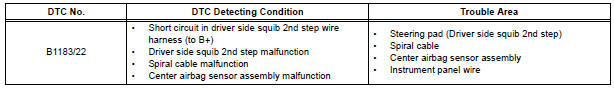
Toyota Sienna Service Manual: Short to B+ in Driver Side Squib 2nd Step Circuit
DTC B1183/22 Short to B+ in Driver Side Squib 2nd Step Circuit
DESCRIPTION
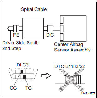
The driver side squib 2nd step circuit consists of the center airbag sensor assembly, the spiral cable and the steering pad.
The circuit instructs the SRS to deploy when deployment conditions are met.
DTC B1183/22 is recorded when a short to B+ is detected in the driver side squib 2nd step circuit.
WIRING DIAGRAM
INSPECTION PROCEDURE
HINT:
- Perform the simulation method by selecting the "check mode" (signal check) with the intelligent tester.
- After selecting the "check mode" (signal check), perform the simulation method by wiggling each connector of the airbag system or driving the vehicle on a city or rough road
1 CHECK STEERING PAD (DRIVER SIDE SQUIB 2ND STEP)
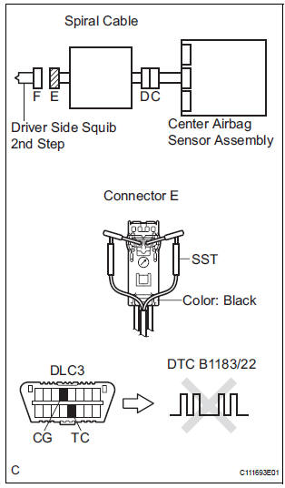
- Turn the ignition switch to the LOCK position.
- Disconnect the negative (-) terminal cable from the battery, and wait for at least 90 seconds
- Disconnect the connectors from the steering pad.
- Connect the white wire side of SST (resistance 2.1 Ω) to
the spiral cable.
CAUTION: Never connect a tester to the steering pad (driver side squib 2nd step) for measurement, as this may lead to a serious injury due to airbag deployment.
NOTICE: Do not forcibly insert the SST into the terminals of the connector when connecting.
Insert the SST straight into the terminals of the connector.
SST 09843-18060
- Connect the negative (-) terminal cable to the battery, and wait for at least 2 seconds.
- Turn the ignition switch to the ON position, and wait for at least 60 seconds.
- Clear the DTCs stored in memory.
- Turn the ignition switch to the LOCK position.
- Turn the ignition switch to the ON position, and wait for at least 60 seconds.
- Check the DTCs.
OK: DTC B1183/22 is not output.
HINT: Codes other than DTC B1183/22 may be output at this time, but they are not related to this check.
REPLACE STEERING PAD
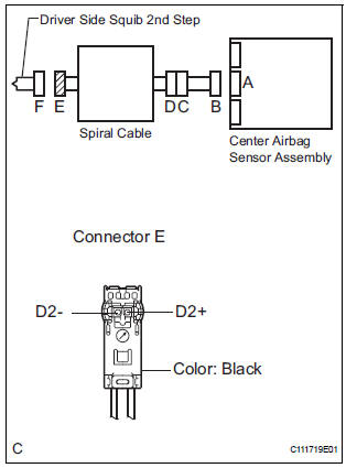
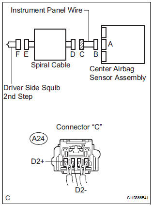
2 CHECK DRIVER SIDE SQUIB 2ND STEP CIRCUIT
- Turn the ignition switch to the LOCK position.
- Disconnect the negative (-) terminal cable from the battery, and wait for at least 90 seconds.
- Disconnect the SST (resistance 2.1 Ω) from the spiral cable.
- Disconnect the connector from the center airbag sensor assembly.
- Connect the negative (-) terminal cable to the battery, and wait for at least 2 seconds.
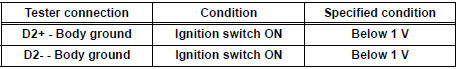
- Turn the ignition switch to the ON position.
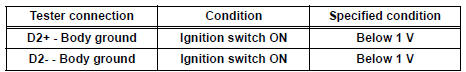
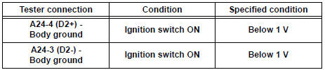
- Measure the voltage according to the value(s) in the table below.
Standard voltage
3 CHECK CENTER AIRBAG SENSOR ASSEMBLY
- Turn the ignition switch to the LOCK position.
- Disconnect the negative (-) terminal cable from the battery, and wait for at least 90 seconds.
- Connect the connectors to the steering pad and the center airbag sensor assembly.
- Connect the negative (-) terminal cable to the battery, and wait for at least 2 seconds.
- Turn the ignition switch to the ON position, and wait for at least 60 seconds.
- Clear the DTCs stored in memory.
- Turn the ignition switch to the LOCK position.
- Turn the ignition switch to the ON position, and wait for at least 60 seconds.
- Check the DTCs.
OK: DTC B1183/22 is not output.
HINT: Codes other than DTC B1183/22 may be output at this time, but they are not related to this check.
USE SIMULATION METHOD TO CHECK
4 CHECK INSTRUMENT PANEL WIRE
- Turn the ignition switch to the LOCK position.
- Disconnect the negative (-) terminal cable from the battery, and wait for at least 90 seconds.
- Disconnect the instrument panel wire connector from the spiral cable.
- Connect the negative (-) terminal cable to the battery, and wait for at least 2 seconds.
- Turn the ignition switch to the ON position.
- Measure the voltage according to the value(s) in the table below.
Standard voltage
5 CHECK SPIRAL CABLE
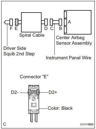
- Measure the voltage according to the value(s) in the table below.
Standard voltage
USE SIMULATION METHOD TO CHECK
 Short to GND in Driver Side Squib 2nd Step Circuit
DTC B1182/19 Short to GND in Driver Side Squib 2nd Step Circuit
DESCRIPTION
The driver side squib 2nd step circuit consists of the center airbag sensor
assembly, the spiral cable and
the steering ...
 Short in Front Passenger Side Squib 2nd Step
Circuit
Short in Front Passenger Side Squib 2nd Step
Circuit
DTC B1185/57 Short in Front Passenger Side Squib 2nd Step
Circuit
DESCRIPTION
The front passenger side squib 2nd step circuit consists of the center airbag
sensor assembly and the
front passenge ...
Other materials:
Warning light and indicator light bulb check
(a) Check the warning lights.
(1) Release parking brake pedal.
(2) When the ignition switch is turned to the ON
position, check that the ABS warning light,
BRAKE warning light, VSC warning light, TRAC
OFF indicator light (2WD) and SLIP indicator
light stay on for approx. 3 seconds.
HI ...
Cold Start Idle Air Control System Performance
DTC P050A Cold Start Idle Air Control System Performance
DESCRIPTION
This monitor will run when the engine is started at -10 to 50C (14 to 122F)
of the engine coolant
temperature. The DTC will set after the engine idling for 13 seconds (2 trip
detection logic).
The DTC is designed to monit ...
Installation
1. INSTALL ROOF HEADLINING ASSEMBLY
w/ sliding roof:
Install the roof headlining with the 5 clips.
w/o sliding roof:
Install the roof headlining with the 3 clips.
NOTICE:
In order to prevent the roof headlining from
becoming bent, work must be performed by 2 or
more persons when ...
