Toyota Sienna Service Manual: Short to B+ in Side Squib RH Circuit
DTC B0113/42 Short to B+ in Side Squib RH Circuit
DESCRIPTION
The side squib RH circuit consists of the center airbag sensor assembly and the front seat side airbag assembly RH.
This circuit instructs the SRS to deploy when deployment conditions are met.
DTC B0113/42 is recorded when a short to B+ is detected in the side squib RH circuit.
|
DTC No. |
DTC Detecting Condition |
Trouble Area |
|
B0113/42 |
|
|
INSPECTION PROCEDURE
HINT:
- Perform the simulation method by selecting the "check mode" (signal check) with the intelligent tester (8).
- After selecting the "check mode" (signal check), perform the simulation method by wiggling each connector of the airbag system or driving the vehicle on a city or rough road
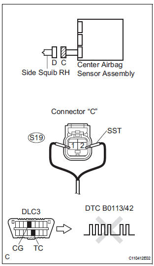
1 CHECK FRONT SEAT SIDE AIRBAG ASSEMBLY RH (SIDE SQUIB RH)
- Turn the ignition switch to the LOCK position.
- Disconnect the negative (-) terminal cable from the battery, and wait for at least 90 seconds.
- Disconnect the connectors from the front seat side airbag assembly RH.
- Connect the black wire side of SST (resistance 2.1 Ω) to the floor wire No. 2.
CAUTION: Never connect a tester to the front seat side airbag assembly RH (side squib RH) for measurement, as this may lead to a serious injury due to airbag deployment.
NOTICE: Do not forcibly insert the SST into the terminals of the connector when connecting.
Insert the SST straight into the terminals of the connector.
SST 09843-18060
- Connect the negative (-) terminal cable to the battery, and wait for at least 2 seconds.
- Turn the ignition switch to the ON position, and wait for at least 60 seconds.
- Clear the DTCs stored in memory (5).
- Turn the ignition switch to the LOCK position.
- Turn the ignition switch to the ON position, and wait for at least 60 seconds.
- Check the DTCs
OK: DTC B0113/42 is not output. HINT: Codes other than DTC B0113/42 may be output at this time, but they are not related to this check.
 Go to step 2

REPLACE FRONT SEAT ASSEMBLY RH
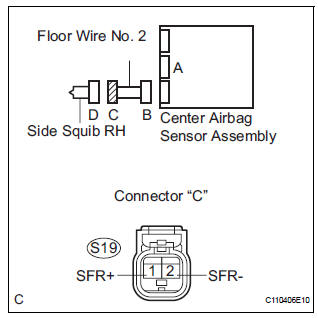
2 CHECK FLOOR WIRE NO.2 (SIDE SQUIB RH CIRCUIT)
- Turn the ignition switch to the LOCK position.
- Disconnect the negative (-) terminal cable from the battery, and wait for at least 90 seconds.
- Disconnect the SST (resistance 2.1 Ω) from the floor wire No. 2.
- Disconnect the connector from the center airbag sensor assembly.
- Connect the negative (-) terminal cable to the battery, and wait for at least 2 seconds.
- Turn the ignition switch to the ON position.
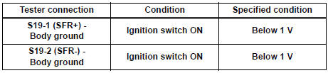
- Measure the voltage according to the value(s) in the table below.
Standard voltage
 REPAIR OR REPLACE FLOOR WIRE
NO.2
REPAIR OR REPLACE FLOOR WIRE
NO.2

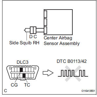
3 CHECK CENTER AIRBAG SENSOR ASSEMBLY
- Turn the ignition switch to the LOCK position.
- Disconnect the negative (-) terminal cable from the battery, and wait for at least 90 seconds.
- Connect the connectors to the front seat side airbag assembly RH and the center airbag sensor assembly.
- Connect the negative (-) terminal cable to the battery, and wait for at least 2 seconds.
- Turn the ignition switch to the ON position, and wait for at least 60 seconds.
- Clear the DTCs stored in memory (5).
- Turn the ignition switch to the LOCK position.
- Turn the ignition switch to the ON position, and wait for at least 60 seconds.
- Check the DTCs (5).
OK: DTC B0113/42 is not output. HINT: Codes other than code B0113/42 may be output at this time, but they are not related to this check.
 REPLACE CENTER AIRBAG SENSOR
ASSEMBLY
REPLACE CENTER AIRBAG SENSOR
ASSEMBLY

USE SIMULATION METHOD TO CHECK
 Short to GND in Side Squib RH Circuit
DTC B0112/41 Short to GND in Side Squib RH Circuit
DESCRIPTION
The side squib RH circuit consists of the center airbag sensor assembly and
the front seat side airbag
assembly RH.
The circuit i ...
 Short in Side Squib LH Circuit
DTC B0115/47 Short in Side Squib LH Circuit
DESCRIPTION
The side squib LH circuit consists of the center airbag sensor assembly and
the front seat side airbag
assembly LH.
This circuit instruc ...
Other materials:
Disposal
HINT:
Use the same procedures for the RH side and LH side.
The procedures listed below are for the LH side.
When scrapping a vehicle equipped with the SRS or
disposing of the curtain shield airbag assembly, be sure to
deploy the airbag first in accordance with the proce ...
Problem symptoms table
SLIDE DOOR CLOSER SYSTEM
Symptom
Suspected Area
Slide door closer LH does not operate (*1)
ECU-B fuse
Power slide door lock assembly LH
Power slide door ECU LH
Wire harness
Slide door closer RH does not operate
ECU-B ...
Disposal
1. DISPOSE OF FRONT SEAT OUTER BELT ASSEMBLY
(WHEN INSTALLED IN VEHICLE)
NOTICE:
Never dispose of a front seat outer belt assembly
with an deactivated pretensioner.
The seat belt pretensioner produces an exploding
sound when it activates, so perform the operation
outdoors w ...
