Toyota Sienna Service Manual: Short to GND in Driver Side Squib 2nd Step Circuit
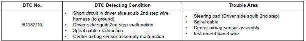
DTC B1182/19 Short to GND in Driver Side Squib 2nd Step Circuit
DESCRIPTION
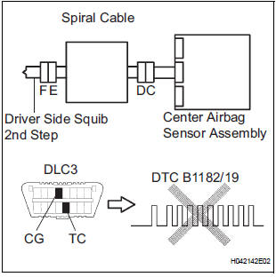
The driver side squib 2nd step circuit consists of the center airbag sensor assembly, the spiral cable and the steering pad.
The circuit instructs the SRS to deploy when deployment conditions are met.
DTC B1182/19 is recorded when a short to ground is detected in the driver side squib 2nd step circuit.
WIRING DIAGRAM
INSPECTION PROCEDURE
HINT:
- Perform the simulation method by selecting the "check mode" (signal check) with the intelligent tester.
- After selecting the "check mode" (signal check), perform the simulation method by wiggling each connector of the airbag system or driving the vehicle on a city or rough road
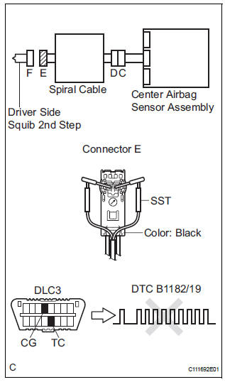
1 CHECK STEERING PAD (DRIVER SIDE SQUIB 2ND STEP)
- Turn the ignition switch to the LOCK position.
- Disconnect the negative (-) terminal cable from the battery, and wait for at least 90 seconds.
- Disconnect the connectors from the steering pad.
- Connect the white wire side of SST (resistance 2.1 Ω) to
the spiral cable.
CAUTION: Never connect a tester to the steering pad (driver side squib 2nd step) for measurement, as this may lead to a serious injury due to airbag deployment.
NOTICE: Do not forcibly insert the SST into the terminals of the connector when connecting.
Insert the SST straight into the terminals of the connector.
SST 09843-18060
- Connect the negative (-) terminal cable to the battery, and wait for at least 2 seconds.
- Turn the ignition switch to the ON position, and wait for at least 60 seconds.
- Clear the DTCs stored in memory.
- Turn the ignition switch to the LOCK position.
- Turn the ignition switch to the ON position, and wait for at least 60 seconds.
- Check the DTCs.
OK: DTC B1182/19 is not output.
HINT: Codes other than DTC B1182/19 may be output at this time, but they are not related to this check.
REPLACE STEERING PAD
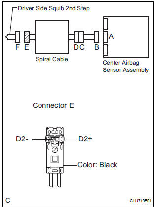
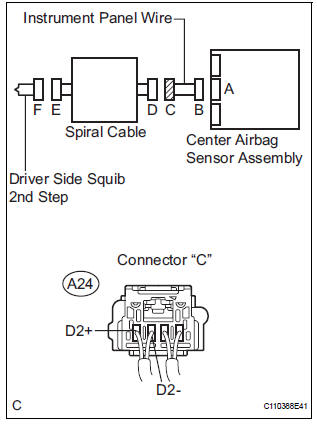
2 CHECK DRIVER SIDE SQUIB 2ND STEP CIRCUIT
- Turn the ignition switch to the LOCK position.
- Disconnect the negative (-) terminal cable from the battery, and wait for at least 90 seconds.
- Disconnect the SST (resistance 2.1 Ω) from the spiral cable.
- Disconnect the connector from the center airbag sensor assembly.
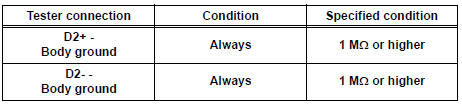
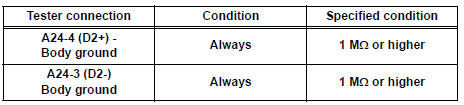
- Measure the resistance according to the value(s) in the table below.
Standard resistance
3 CHECK CENTER AIRBAG SENSOR ASSEMBLY
- Connect the connectors to the steering pad and the center airbag sensor assembly.
- Connect the negative (-) terminal cable to the battery, and wait for at least 2 seconds.
- Turn the ignition switch to the ON position, and wait for at least 60 seconds.
- Clear the DTCs stored in memory.
- Turn the ignition switch to the LOCK position.
- Turn the ignition switch to the ON position, and wait for at least 60 seconds.
- Check the DTCs.
OK: DTC B1182/19 is not output.
HINT: Codes other than DTC B1182/19 may be output at this time, but they are not related to this check.
USE SIMULATION METHOD TO CHECK
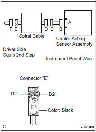
4 CHECK INSTRUMENT PANEL WIRE
- Disconnect the instrument panel wire connector from the spiral cable.
- Measure the resistance according to the value(s) in the table below.
Standard resistance
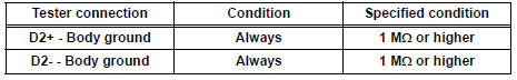
5 CHECK SPIRAL CABLE
- Measure the resistance according to the value(s) in the table below.
Standard resistance
USE SIMULATION METHOD TO CHECK
 Open in Driver Side Squib 2nd Step Circuit
DTC B1181/18 Open in Driver Side Squib 2nd Step Circuit
DESCRIPTION
The driver side squib 2nd step circuit consists of the center airbag sensor
assembly, the spiral cable and
the steering pad.
...
 Short to B+ in Driver Side Squib 2nd Step Circuit
DTC B1183/22 Short to B+ in Driver Side Squib 2nd Step Circuit
DESCRIPTION
The driver side squib 2nd step circuit consists of the center airbag sensor
assembly, the spiral cable and
the steering ...
Other materials:
Transfer system
PRECAUTION
NOTICE:
1. Before disassembly, clean the transfer assembly of
any sand or mud to prevent it from entering inside the
transfer during disassembly and assembly.
2. When removing any light alloy part such as a transfer
cover, do not pry it off with a tool like a screwdriver,
but tap ...
Inspection
1. INSPECT FRONT STABILIZER LINK ASSEMBLY LH
(a) As shown in the illustration, flip the ball joint stud
back and forth 5 times, before installing the nut.
(b) Using a torque wrench, turn the nut continuously at
a rate of 2 to 4 seconds per 1 turn and take the
torque reading on the 5th tur ...
Installation
1. INSTALL TIMING CHAIN CASE OIL SEAL
(a) Using SST, tap in a new oil seal until its surface is
flush with the timing chain case edge.
SST 09223-22010, 09506-35010
NOTICE:
Keep the lip free from foreign matter.
Do not tap on the oil seal at an angle.
Make sure that the oil ...
