Toyota Sienna Service Manual: Short to GND in Front Passenger Side Squib 2nd Step Circuit
DTC B1187/55 Short to GND in Front Passenger Side Squib 2nd Step Circuit
DESCRIPTION
The front passenger side squib 2nd step circuit consists of the center airbag sensor assembly and the front passenger airbag assembly.
The circuit instructs the SRS to deploy when deployment conditions are met.
DTC B1187/55 is recorded when a short to ground is detected in the front passenger side squib 2nd step circuit.
|
DTC No. |
DTC Detecting Condition |
Trouble Area |
|
B1187/55 |
|
|
INSPECTION PROCEDURE
HINT:
- Perform the simulation method by selecting the "check mode" (signal check) with the intelligent tester (8).
- After selecting the "check mode" (signal check), perform the simulation method by wiggling each connector of the airbag system or driving the vehicle on a city or rough road
1 CHECK FRONT PASSENGER AIRBAG ASSEMBLY (FRONT PASSENGER SIDE SQUIB 2ND STEP)
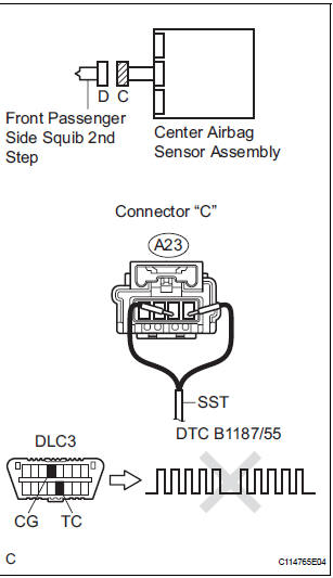
- Turn the ignition switch to the LOCK position.
- Disconnect the negative (-) terminal cable from the battery, and wait for at least 90 seconds.
- Disconnect the connectors from the front passenger airbag assembly.
- Connect the black wire side of SST (resistance 2.1 Ω) to the instrument panel wire.
CAUTION: Never connect a tester to the front passenger airbag assembly (front passenger side squib 2nd step) for measurement, as this may lead to a serious injury due to airbag deployment.
NOTICE: Do not forcibly insert the SST into the terminals of the connector when connecting.
Insert the SST straight into the terminals of the connector.
SST 09843-18060
- Connect the negative (-) terminal cable to the battery, and wait for at least 2 seconds.
- Turn the ignition switch to the ON position, and wait for at least 60 seconds.
- Clear the DTCs stored in memory (5).
- Turn the ignition switch to the LOCK position.
- Turn the ignition switch to the ON position, and wait for at least 60 seconds.
- Check the DTCs (5).
OK: DTC B1187/55 is not output. HINT: Codes other than DTC B1187/55 may be output at this time, but they are not related to this check.
 Go to step 2

REPLACE FRONT PASSENGER AIRBAG ASSEMBLY
2 CHECK INSTRUMENT PANEL WIRE (FRONT PASSENGER SIDE SQUIB 2ND STEP CIRCUIT)
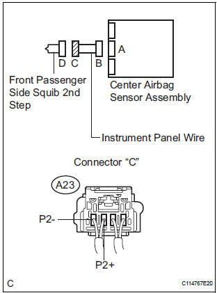
- Turn the ignition switch to the LOCK position.
- Disconnect the negative (-) terminal cable from the battery, and wait for at least 90 seconds.
- Disconnect the SST (resistance 2.1 Ω) from the instrument panel wire.
- Disconnect the connector from the center airbag sensor assembly.
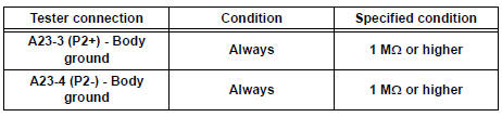
- Measure the resistance according to the value(s) in the table below.
Standard resistance
 REPAIR OR REPLACE INSTRUMENT
PANEL
WIRE
REPAIR OR REPLACE INSTRUMENT
PANEL
WIRE

3 CHECK CENTER AIRBAG SENSOR ASSEMBLY
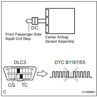
- Connect the connectors to the front passenger airbag assembly and the center airbag sensor assembly.
- Connect the negative (-) terminal cable to the battery, and wait for at least 2 seconds.
- Turn the ignition switch to the ON position, and wait for at least 60 seconds.
- Clear the DTCs stored in memory (5).
- Turn the ignition switch to the LOCK position.
- Turn the ignition switch to the ON position, and wait for at least 60 seconds.
- Check the DTCs (5).
OK: DTC B1187/55 is not output. HINT: Codes other than DTC B1187/55 may be output at this time, but they are not related to this check.
 REPLACE CENTER AIRBAG SENSOR
ASSEMBLY
REPLACE CENTER AIRBAG SENSOR
ASSEMBLY

USE SIMULATION METHOD TO CHECK
 Open in Front Passenger Side Squib 2nd Step
Circuit
Open in Front Passenger Side Squib 2nd Step
Circuit
DTC B1186/58 Open in Front Passenger Side Squib 2nd Step
Circuit
DESCRIPTION
The front passenger side squib 2nd step circuit consists of the center airbag
sensor assembly and the
front passenger ...
 Short to B+ in Front Passenger Side Squib 2nd
Step Circuit
Short to B+ in Front Passenger Side Squib 2nd
Step Circuit
DTC B1188/56 Short to B+ in Front Passenger Side Squib 2nd
Step Circuit
DESCRIPTION
The front passenger side squib 2nd step circuit consists of the center airbag
sensor assembly and the
front pa ...
Other materials:
Diagnostic trouble code chart
If a malfunction code is displayed during the DTC check,
check the circuit listed for that code in the table below.
(Proceed to the page given for that circuit.)
POWER BACK DOOR SYSTEM
DTC No.
Detection Item
Trouble Area
B2222
PBD Pulse Sensor Malfuncti ...
Inspection
1. INSPECT BRAKE DISC INSIDE DIAMETER
(a) Using a brake drum gauge or equivalent, measure
the inside diameter of the disc.
Standard inside diameter:
190 mm (7.480 in.)
Maximum inside diameter:
191 mm (7.520 in.)
2. INSPECT PARKING BRAKE SHOE LINING THICKNESS
(a) Using a ruler, measur ...
Fold Lock Switch Circuit
DESCRIPTION
Each of the left and right seats has a fold lock switch that detects the lock
condition of the seat legs and
floor when the seat is in the stowed state. If the fold lock switch detects an
unlock condition, the 3rd SEAT
indicator on the combination meter will come on.
WIRING DIAGR ...
