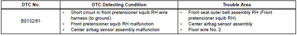
Toyota Sienna Service Manual: Short to GND in Front Pretensioner Squib RH Circuit
DTC B0132/61 Short to GND in Front Pretensioner Squib RH Circuit
DESCRIPTION
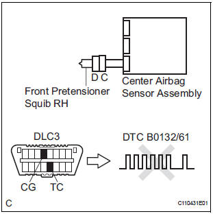
The front pretensioner squib RH circuit consists of the center airbag sensor assembly and the front seat outer belt assembly RH.
This circuit instructs the SRS to deploy when deployment conditions are met.
DTC B0132/61 is recorded when a short to ground is detected in the front pretensioner squib RH circuit.
WIRING DIAGRAM
INSPECTION PROCEDURE
HINT:
- Perform the simulation method by selecting the "check mode" (signal check) with the intelligent tester.
- After selecting the "check mode" (signal check), perform the simulation method by wiggling each connector of the airbag system or driving the vehicle on a city or rough road
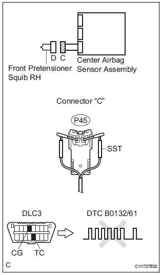
1 CHECK FRONT SEAT OUTER BELT ASSEMBLY RH (FRONT PRETENSIONER SQUIB RH)
- Turn the ignition switch to the LOCK position.
- Disconnect the negative (-) terminal cable from the battery, and wait for at least 90 seconds.
- Disconnect the connectors from the front seat outer belt assembly RH.
- Connect the white wire side of SST (resistance 2.1 Ω) to the floor wire No. 2.
CAUTION: Never connect a tester to the front seat outer belt assembly RH (front pretensioner squib RH) for measurement, as this may lead to a serious injury due to airbag deployment.
NOTICE: Do not forcibly insert the SST into the terminals of the connector when connecting.
Insert the SST straight into the terminals of the connector.
SST 09843-18060
- Connect the negative (-) terminal cable to the battery, and wait for at least 2 seconds.
- Turn the ignition switch to the ON position, and wait for at least 60 seconds.
- Clear the DTCs stored in memory.
- Turn the ignition switch to the LOCK position.
- Turn the ignition switch to the ON position, and wait for at least 60 seconds.
- Check the DTCs.
OK: DTC B0132/61 is not output.
HINT: Codes other than DTC B0132/61 may be output at this time, but they are not related to this check.
REPLACE FRONT SEAT OUTER BELT ASSEMBLY RH
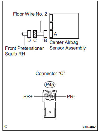
2 CHECK FLOOR WIRE NO.2 (FRONT PRETENSIONER SQUIB RH CIRCUIT)
- Turn the ignition switch to the LOCK position.
- Disconnect the negative (-) terminal cable from the battery, and wait for at least 90 seconds.
- Disconnect the SST (resistance 2.1 Ω) from the floor wire No. 2.
- Disconnect the connector from the center airbag sensor assembly.
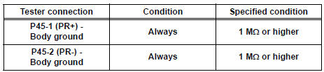
- Measure the resistance according to the value(s) in the table below.
Standard resistance
3 CHECK CENTER AIRBAG SENSOR ASSEMBLY
- Connect the connectors to the front seat outer belt assembly RH and the center airbag sensor assembly.
- Connect the negative (-) terminal cable to the battery, and wait for at least 2 seconds.
- Turn the ignition switch to the ON position, and wait for at least 60 seconds.
- Clear the DTCs stored in memory.
- Turn the ignition switch to the LOCK position.
- Turn the ignition switch to the ON position, and wait for at least 60 seconds.
- Check the DTCs.
OK: DTC B0132/61 is not output.
HINT: Codes other than code B0132/61 may be output at this time, but they are not related to this check.
USE SIMULATION METHOD TO CHECK
 Open in Front Pretensioner Squib RH Circuit
DTC B0131/64 Open in Front Pretensioner Squib RH Circuit
DESCRIPTION
The front pretensioner squib RH circuit consists of the center airbag sensor
assembly and the front seat
outer belt assembly R ...
 Short to B+ in Front Pretensioner Squib RH Circuit
DTC B0133/62 Short to B+ in Front Pretensioner Squib RH Circuit
DESCRIPTION
The front pretensioner squib RH circuit consists of the center airbag sensor
assembly and the front seat
outer belt ass ...
Other materials:
Steering Angle Sensor Circuit Malfunction
DTC C1231/31 Steering Angle Sensor Circuit Malfunction
DESCRIPTION
The steering angle sensor signal is sent to the skid control ECU through the
CAN communication system.
When there is a malfunction in the communication, it will be detected by the
diagnosis function.
WIRING DIAGRAM
INS ...
Identification of noise source
1. Radio Description
Radio frequency band
Radio broadcasts use the radio frequency bands
shown in the table below.
Service area
The service areas of AM and FM broadcasts are
vastly different. Sometimes an AM broadcast
can be received very clearly ...
Disassembly
1. HOLD VANE PUMP ASSEMBLY
(a) Using SST, hold the vane pump assembly in a vise.
SST 09630-00014 (09631-00132)
2. REMOVE POWER STEERING SUCTION PORT UNION
(a) Remove the bolt and the power steering suction port
union from the vane pump front housing.
(b) Using a screwdriver, remove ...
