Toyota Sienna Service Manual: Short to GND in Side Squib RH Circuit
DTC B0112/41 Short to GND in Side Squib RH Circuit
DESCRIPTION
The side squib RH circuit consists of the center airbag sensor assembly and the front seat side airbag assembly RH.
The circuit instructs the SRS to deploy when deployment conditions are met.
DTC B0112/41 is recorded when a short to ground is detected in the side squib RH circuit.
|
DTC No. |
DTC Detecting Condition |
Trouble Area |
|
B0112/41 |
|
|
INSPECTION PROCEDURE
HINT:
- Perform the simulation method by selecting the "check mode" (signal check) with the intelligent tester (8).
- After selecting the "check mode" (signal check), perform the simulation method by wiggling each connector of the airbag system or driving the vehicle on a city or rough road
1 CHECK FRONT SEAT SIDE AIRBAG ASSEMBLY RH (SIDE SQUIB RH)
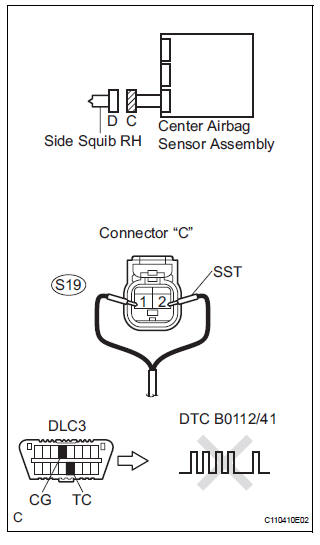
- Turn the ignition switch to the LOCK position.
- Disconnect the negative (-) terminal cable from the battery, and wait for at least 90 seconds.
- Disconnect the connectors from the front seat side airbag assembly RH.
- Connect the black wire side of SST (resistance 2.1 Ω) to the floor wire No. 2.
CAUTION: Never connect a tester to the front seat side airbag assembly RH (side squib RH) for measurement, as this may lead to a serious injury due to airbag deployment.
NOTICE: Do not forcibly insert the SST into the terminals of the connector when connecting.
Insert the SST straight into the terminals of the connector.
SST 09843-18060
- Connect the negative (-) terminal cable to the battery, and wait for at least 2 seconds.
- Turn the ignition switch to the ON position, and wait for at least 60 seconds.
- Clear the DTCs stored in memory (5).
- Turn the ignition switch to the LOCK position.
- Turn the ignition switch to the ON position, and wait for at least 60 seconds.
- Check the DTCs
OK: DTC B0112/41 is not output.
HINT: Codes other than DTC B0112/41 may be output at this time, but they are not related to this check.
 Go to step 2

REPLACE FRONT SEAT ASSEMBLY RH
2 CHECK FLOOR WIRE NO.2 (SIDE SQUIB RH CIRCUIT)
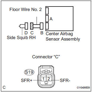
- Turn the ignition switch to the LOCK position.
- Disconnect the negative (-) terminal cable from the battery, and wait for at least 90 seconds.
- Disconnect the SST (resistance 2.1 Ω) from the floor wire No. 2.
- Disconnect the connector from the center airbag sensor assembly.
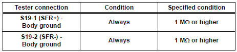
- Measure the resistance according to the value(s) in the table below.
Standard resistance
 REPAIR OR REPLACE FLOOR WIRE
NO.2
REPAIR OR REPLACE FLOOR WIRE
NO.2

3 CHECK CENTER AIRBAG SENSOR ASSEMBLY
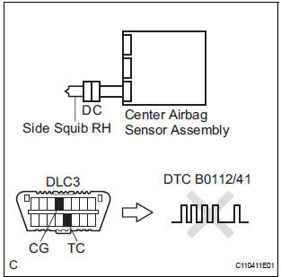
- Connect the connectors to the front seat side airbag assembly RH and the center airbag sensor assembly.
- Connect the negative (-) terminal cable to the battery, and wait for at least 2 seconds.
- Turn the ignition switch to the ON position, and wait for at least 60 seconds.
- Clear the DTCs stored in memory (5).
- Turn the ignition switch to the LOCK position.
- Turn the ignition switch to the ON position, and wait for at least 60 seconds.
- Check the DTCs (5).
OK: DTC B0112/41 is not output. HINT: Codes other than code B0112/41 may be output at this time, but they are not related to this check.
REPLACE CENTER AIRBAG SENSOR
ASSEMBLY
USE SIMULATION METHOD TO CHECK
 Open in Side Squib RH Circuit
DTC B0111/44 Open in Side Squib RH Circuit
DESCRIPTION
The side squib RH circuit consists of the center airbag sensor assembly and
the front seat side airbag
assembly RH.
The circuit instructs ...
 Short to B+ in Side Squib RH Circuit
DTC B0113/42 Short to B+ in Side Squib RH Circuit
DESCRIPTION
The side squib RH circuit consists of the center airbag sensor assembly and
the front seat side airbag
assembly RH.
This circuit i ...
Other materials:
Radio Receiver Communication Error
INSPECTION PROCEDURE
1 IDENTIFY THE COMPONENT SHOWN BY THE SUB-CODE
Enter the diagnostic mode
Press the preset switch "3" to change to "Detailed
Information Mode".
Identify the component shown by the sub-code.
HINT:
"190 (radio receiver) ...
EVAP System
RELATED DTCS
If any EVAP system DTCs are set, the malfunctioning area can be determined
using the table below.
NOTICE:
If the 0.02 inch reference pressure difference between the first and second
checks is greater than
the specification, the DTCs corresponding to the reference pressur ...
Radio antenna pole
COMPONENTS
REMOVAL
1. REMOVE PULL TOP ANTENNA POLE SUBASSEMBLY
Remove the pull top antenna pole sub-assembly by
pulling it the arrow direction in the illustration.
INSTALLATION
1. INSTALL PULL TOP ANTENNA POLE SUBASSEMBLY ...
