Toyota Sienna Service Manual: Short to GND in Side Squib RH Circuit
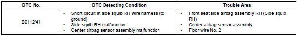
DTC B0112/41 Short to GND in Side Squib RH Circuit
DESCRIPTION
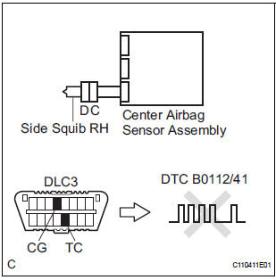
The side squib RH circuit consists of the center airbag sensor assembly and the front seat side airbag assembly RH.
The circuit instructs the SRS to deploy when deployment conditions are met.
DTC B0112/41 is recorded when a short to ground is detected in the side squib RH circuit.
WIRING DIAGRAM
INSPECTION PROCEDURE
HINT:
- Perform the simulation method by selecting the "check mode" (signal check) with the intelligent tester.
- After selecting the "check mode" (signal check), perform the simulation method by wiggling each connector of the airbag system or driving the vehicle on a city or rough road
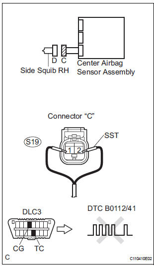
1 CHECK FRONT SEAT SIDE AIRBAG ASSEMBLY RH (SIDE SQUIB RH)
- Turn the ignition switch to the LOCK position.
- Disconnect the negative (-) terminal cable from the battery, and wait for at least 90 seconds.
- Disconnect the connectors from the front seat side airbag assembly RH.
- Connect the black wire side of SST (resistance 2.1 Ω) to the floor wire No. 2.
CAUTION: Never connect a tester to the front seat side airbag assembly RH (side squib RH) for measurement, as this may lead to a serious injury due to airbag deployment.
NOTICE: Do not forcibly insert the SST into the terminals of the connector when connecting.
Insert the SST straight into the terminals of the connector.
SST 09843-18060
- Connect the negative (-) terminal cable to the battery, and wait for at least 2 seconds.
- Turn the ignition switch to the ON position, and wait for at least 60 seconds.
- Clear the DTCs stored in memory.
- Turn the ignition switch to the LOCK position.
- Turn the ignition switch to the ON position, and wait for at least 60 seconds.
- Check the DTCs
OK: DTC B0112/41 is not output.
HINT: Codes other than DTC B0112/41 may be output at this time, but they are not related to this check.
REPLACE FRONT SEAT ASSEMBLY RH
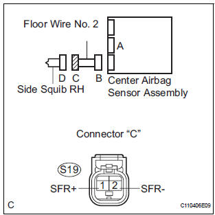
2 CHECK FLOOR WIRE NO.2 (SIDE SQUIB RH CIRCUIT)
- Turn the ignition switch to the LOCK position.
- Disconnect the negative (-) terminal cable from the battery, and wait for at least 90 seconds.
- Disconnect the SST (resistance 2.1 Ω) from the floor wire No. 2.
- Disconnect the connector from the center airbag sensor assembly.
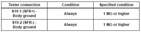
- Measure the resistance according to the value(s) in the table below.
Standard resistance
3 CHECK CENTER AIRBAG SENSOR ASSEMBLY
- Connect the connectors to the front seat side airbag assembly RH and the center airbag sensor assembly.
- Connect the negative (-) terminal cable to the battery, and wait for at least 2 seconds.
- Turn the ignition switch to the ON position, and wait for at least 60 seconds.
- Clear the DTCs stored in memory.
- Turn the ignition switch to the LOCK position.
- Turn the ignition switch to the ON position, and wait for at least 60 seconds.
- Check the DTCs.
OK: DTC B0112/41 is not output.
HINT: Codes other than code B0112/41 may be output at this time, but they are not related to this check.
USE SIMULATION METHOD TO CHECK
 Open in Side Squib RH Circuit
DTC B0111/44 Open in Side Squib RH Circuit
DESCRIPTION
The side squib RH circuit consists of the center airbag sensor assembly and
the front seat side airbag
assembly RH.
The circuit instructs ...
 USE SIMULATION METHOD TO CHECK
DTC B0113/42 Short to B+ in Side Squib RH Circuit
DESCRIPTION
The side squib RH circuit consists of the center airbag sensor assembly and
the front seat side airbag
assembly RH.
This circuit i ...
Other materials:
Stereo component amplifier
COMPONENTS
Removal
1. REMOVE GLOVE COMPARTMENT DOOR ASSEMBLY
2. REMOVE STEREO COMPONENT AMPLIFIER ASSEMBLY
Disconnect the connectors.
Remove the 2 nuts and the stereo component
amplifier assembly.
Installation
1. INSTALL STEREO COMPONENT AMPLIFIER ASSEMBLY
...
Problem symptoms table
If there are no DTCs output but the problem still occurs,
check the circuits for each problem symptom in the order
given in the table below and proceed to the relevant
troubleshooting page.
NOTICE:
When replacing the brake actuator assembly, sensor,
etc., turn the ignition switch off.
HINT:
...
Sound Signal Circuit between Radio Receiver and Stereo Component
Amplifier
DESCRIPTION
The radio receiver sends a sound signal to the stereo component amplifier
through this circuit.
The sound signal that has been sent is amplified by the stereo component
amplifier, and then is sent to
the speakers.
If there is an open or short in the circuit, sound cannot be h ...
