Toyota Sienna Service Manual: Sound Signal Circuit between Radio and Navigation Assembly and Television Display Assembly
DESCRIPTION
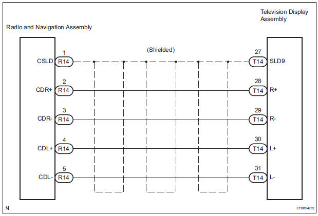
The television display assembly sends an RSE sound signal to the radio and navigation assembly through this circuit. The sound signal that has been sent is amplified by the stereo component amplifier, and then is sent to the speakers.
If there is an open or short in the circuit, sound cannot be heard from the speakers even if there is no malfunction in the stereo component amplifier, radio and navigation assembly or speakers.
WIRING DIAGRAM
INSPECTION PROCEDURE
1 CHECK HARNESS AND CONNECTOR (RADIO AND NAVIGATION ASSEMBLY - TELEVISION DISPLAY ASSEMBLY)
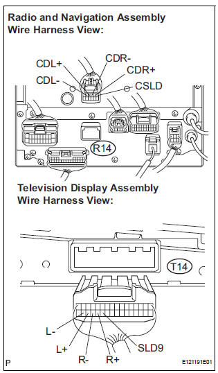
- Disconnect the connectors from the television display assembly and radio and navigation assembly.
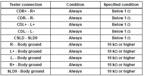
- Measure the resistance according to the value(s) in the table below.
Standard resistance
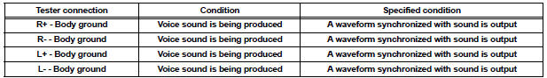
2 INSPECT TELEVISION DISPLAY ASSEMBLY
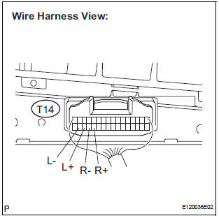
- Reconnect the television display assembly connector and radio and navigation assembly connectors.
- Check the waveform according to the conditions in the table below
Standard resistance
PROCEED TO NEXT CIRCUIT INSPECTION SHOWN IN PROBLEM SYMPTOMS TABLE
 Speaker Circuit
DESCRIPTION
The sound signal that has been amplified by the stereo component amplifier is
sent to the speakers from
the stereo component amplifier through this circuit.
If there is a short in t ...
 Sound Signal Circuit between Radio and Navigation Assembly and
Stereo Component Amplifier
Sound Signal Circuit between Radio and Navigation Assembly and
Stereo Component Amplifier
DESCRIPTION
The radio and navigation assembly sends a sound signal to the stereo
component amplifier through this
circuit.
The sound signal that has been sent is amplified by the stereo compone ...
Other materials:
Definition of terms
Term
Definition
Monitor description
Description of what the ecm monitors and how it detects malfunctions
(monitoring purpose and its details).
Related dtcs
Diagnostic codeV
Typical enabling condition
Preconditions that allow the ecm to detect malfunc ...
Open in CAN Main Bus Line
DESCRIPTION
There may be an open circuit in the CAN main bus wire and/or the DLC3 branch
wire when the resistance
between terminals 6 (CANH) and 14 (CANL) of the DLC3 is 69 Ω or higher.
Symptom
Trouble Area
Resistance between terminals 6 (CANH) and 14 (CANL) of t ...
Sensor signal check by test mode (signal check) (when using sst check wire)
(a) When having replaced the skid control ECU and/or
yaw rate and deceleration sensor, perform zero
point calibration of the yaw rate and deceleration
sensor.
HINT:
If the ignition switch is turned from the ON
position to the ACC or off during test mode
(signal check), DTCs of the signal ...
