Toyota Sienna Service Manual: Sound Signal Circuit between Radio Receiver and Television Display Assembly
DESCRIPTION
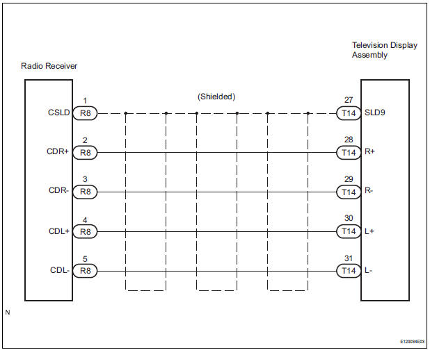
The television display assembly sends a sound signal to the radio receiver through this circuit.
The sound signal that has been sent is amplified by the stereo component amplifier or radio receiver (built-in amplifier), and then is sent to the speakers.
If there is an open or short in the circuit, sound cannot be heard from the speakers even if there is no malfunction in the stereo component amplifier, radio receiver, or speakers.
WIRING DIAGRAM
INSPECTION PROCEDURE
1 CHECK HARNESS AND CONNECTOR (RADIO RECEIVER - TELEVISION DISPLAY ASSEMBLY)
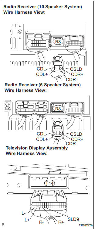
- Disconnect the connectors from the television display assembly and radio receiver.
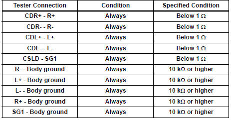
- Measure the resistance according to the value(s) in the table below.
Standard resistance
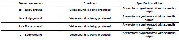
2 INSPECT TELEVISION DISPLAY ASSEMBLY
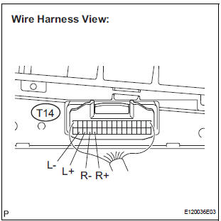
- Reconnect the television display assembly connector.
- Check the waveform according to the conditions shown in the table below
Standard
PROCEED TO NEXT CIRCUIT INSPECTION SHOWN IN PROBLEM SYMPTOMS TABLE
 Sound Signal Circuit between Radio Receiver and Stereo Component
Amplifier
Sound Signal Circuit between Radio Receiver and Stereo Component
Amplifier
DESCRIPTION
The radio receiver sends a sound signal to the stereo component amplifier
through this circuit.
The sound signal that has been sent is amplified by the stereo component
amplifier, ...
 Sound Signal Circuit between Radio Receiver and Stereo Jack Adapter
DESCRIPTION
The stereo jack adapter sends an external device sound signal to the radio
receiver through this circuit.
The sound signal that has been sent is amplified by the stereo component
a ...
Other materials:
Installation
1. INSTALL REAR DOOR GLASS WEATHERSTRIP
Install the rear door glass weatherstrip.
2. INSTALL SLIDE DOOR WINDOW ASSEMBLY
3. INSTALL REAR DOOR GLASS RUN
4. INSTALL REAR DOOR TRIM BOARD SUBASSEMBLY
5. INSTALL SIDE TRIM BOARD COVER REAR
6. INSTALL REAR DOOR WINDOW FRAME SUBASSEMBLY
7. INSTA ...
Customizing vehicle features
Changing using the audio system screen
Audio system with “CAR” button
Press the “SETUP” button.
Select “Vehicle” on the “Setup” screen.
Audio system with “APPS” button
Press the “APPS” button.
Select “Setup” on the “Apps” screen and select †...
Fastening the seat belt (for the third center seat)
Take the plate out of the holder,
and then pull down the seat
belt.
Push plate “A” into buckle “A”
until a click sound is heard.
Push plate “B” into buckle “B”
until a click sound is heard.
...
