Toyota Sienna Service Manual: Speed Signal Circuit
DESCRIPTION
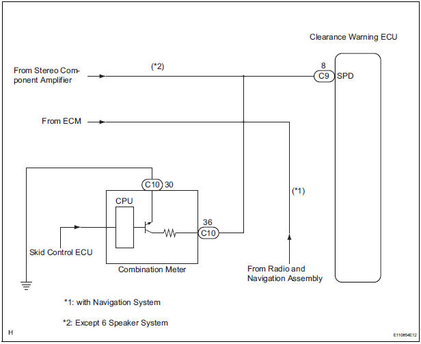
The clearance warning ECU receives the vehicle speed signal from the combination meter.
HINT:
- A voltage of 12 V or 5 V is output from each ECU and then input to the combination meter. The signal is changed to a pulse signal at the transistor in the combination meter. Each ECU controls the respective system based on the pulse signal.
- If a short occurs in an ECU, all systems in the diagram below will not operate normally.
WIRING DIAGRAM
INSPECTION PROCEDURE
1 CHECK OPERATION OF SPEEDOMETER
- Drive the vehicle and check if the function of the speedometer in the combination meter is normal.
OK: Actual vehicle speed and the speed indicated on the speedometer are the same.
HINT: The vehicle speed signal is normal when the indication on the speedometer is normal.
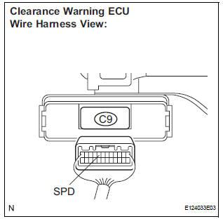
2 INSPECT CLEARANCE WARNING ECU
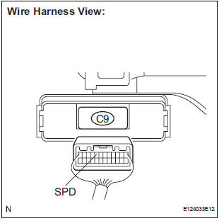
- Disconnect the clearance warning ECU connector C9.
- Measure the voltage.
- Jack up either one of the drive wheels.
- Move the shift lever to the neutral position.
- Turn the ignition switch to the ON position
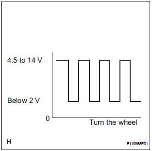
- Measure the voltage between terminal SPD of the clearance warning ECU and body ground when a drive wheel is turned slowly.
OK: Voltage pulses as shown.
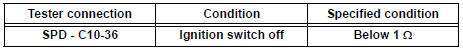
3 CHECK HARNESS AND CONNECTOR (COMBINATION METER - CLEARANCE WARNING ECU)
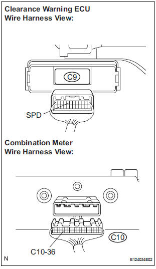
- Disconnect the combination meter C10 connector.
- Measure the resistance according to the value(s) in the table below.
Standard resistance
4 CHECK HARNESS AND CONNECTOR (COMBINATION METER AND EACH ECU - BODY GROUND)
- Measure the resistance according to the value(s) in the table below.
Standard resistance
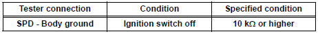
HINT: If the resistance between terminal SPD and body ground is less than 10 kΩ, there may be a short in a wire harness, connector, or ECU.
REPLACE COMBINATION METER
 Park / Neutral Position Switch Circuit
DESCRIPTION
The clearance warning ECU receives the reverse or park position signal from
the park / neutral position
switch.
WIRING DIAGRAM
INSPECTION PROCEDURE
1 INSPECT CLEARANCE WARNING E ...
 Back Sonar Sensor LH Circuit
DESCRIPTION
An ultrasonic sensor consists of a sensor portion that transmits and receives
ultrasonic waves and a preamplifier
that amplifies them. The ultrasonic sensor outputs the ultrasonic wave ...
Other materials:
Installation
1. INSTALL BRAKE VACUUM CHECK VALVE
ASSEMBLY
(a) Install the brake vacuum check valve assembly and
check valve grommet to the brake booster
assembly.
2. INSTALL BRAKE BOOSTER GASKET
(a) Install a new brake booster gasket to the brake
booster with master cylinder.
3. INSTALL BRAKE MASTER CYLI ...
Transmission Fluid Temperature Sensor "A"
DESCRIPTION
The ATF (Automatic Transmission Fluid) temperature sensor converts the fluid
temperature into a
resistance value which is input into the ECM.
The ECM applies a voltage to the temperature sensor through ECM terminal THO1.
The sensor resistance changes with the transmission f ...
Removal
1. REMOVE REAR DOOR SCUFF PLATE LH
2. REMOVE REAR DOOR WEATHERSTRIP LH
3. REMOVE BACK DOOR WEATHERSTRIP
4. REMOVE BACK DOOR SCUFF PLATE
5. REMOVE QUARTER TRIM FRONT PANEL ASSEMBLY LH
6. REMOVE POWER POINT SOCKET ASSEMBLY
Release the 2 claw fittings and remove the power
point soc ...
