Toyota Sienna Service Manual: Speedometer Malfunction
DESCRIPTION
Factors that affect the indicated vehicle speed include tire size, tire inflation, and tire wear. The speed indicated on the speedometer has an allowable margin of error. This can be tested using a speedometer tester (calibrated chassis dynamometer). For details about testing and the margin of error, see the reference chart.
WIRING DIAGRAM
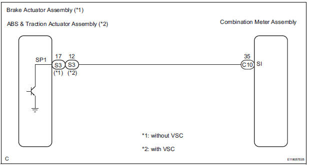
INSPECTION PROCEDURE
NOTICE: If the vehicle speed is outside the allowable range when tested, perform the following procedure.
1 PERFORM ACTIVE TEST BY INTELLIGENT TESTER
- Connect the tester to the DLC3.
- Turn the ignition switch to the ON position.
- Turn the tester ON.
- Enter the following menus: DIAGNOSIS / OBD/MOBD / METER / ACTIVE TEST
- Check the operation by referring to the values in the table below.
METER:

*1: for U.S.A.
*2: Except for U.S.A.
OK: Needle indication is within the allowable range.
2 READ VALUE OF INTELLIGENT TESTER
- Connect the intelligent tester to the DLC3.
- Turn the ignition switch to the ON position.
- Turn the tester ON.
- Enter the following menus: DIAGNOSIS / OBD/MOBD / METER / DATA LIST.
- Check the values by referring to the values in the table below.
METER:

OK: Vehicle speed displayed on the tester is almost the same as the actual vehicle speed measured using a speedometer tester (calibrated chassis dynamometer).
REPLACE COMBINATION METER ASSEMBLY
3 READ VALUE OF INTELLIGENT TESTER
- Connect the intelligent tester to the DLC3.
- Turn the ignition switch to the ON position.
- Turn the tester ON.
- Enter the following menus: DIAGNOSIS / ABS/TRAC/ VSC / DATA LIST.
- Check the values by referring to the values in the table below.
ABS/TRAC/VSC:

OK: Vehicle speed displayed on the tester is almost the same as the actual vehicle speed measured using a speedometer tester (calibrated chassis dynamometer).
4 INSPECT COMBINATION METER ASSEMBLY
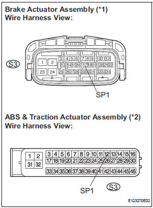
- Disconnect the S3 connector.
- Measure the voltage according to the value(s) in the table below.
Standard voltage
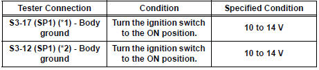
*1: without VSC
*2: with VSC
Result
5 INSPECT COMBINATION METER ASSEMBLY
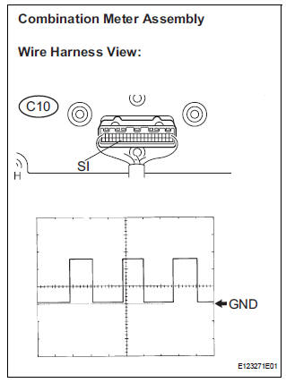
- Check the input signal waveform.
- Remove the combination meter assembly with connector(s) still connected.
- Connect the oscilloscope to terminal C10-35 (SI) and body ground.
- Turn the wheel slowly.
- Check the signal waveform according to the condition(s) in the table below.
OK: The waveform is displayed as shown in the illustration.
HINT: As the vehicle speed increases, the cycle of the signal waveform narrows.
Result
REPLACE COMBINATION METER ASSEMBLY
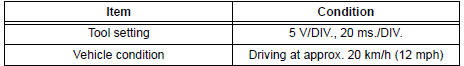
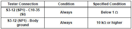
6 CHECK HARNESS AND CONNECTOR (COMBINATION METER - BRAKE ACTUATOR ASSEMBLY)
- Disconnect the S3 and C10 connectors.
- Measure the resistance according to the value(s) in the table below.
Standard resistance
REPLACE COMBINATION METER ASSEMBLY
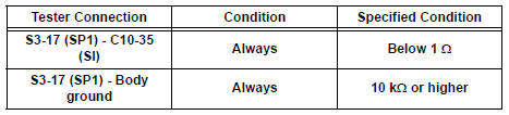
7 CHECK HARNESS AND CONNECTOR (COMBINATION METER - ABS & TRACTION ACTUATOR ASSEMBLY)
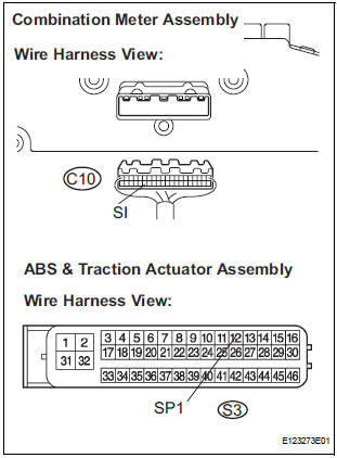
- Disconnect the S3 and C10 connectors.
- Measure the resistance according to the value(s) in the table below.
Standard resistance
REPLACE COMBINATION METER ASSEMBLY
 Entire Combination Meter does not Operate
DESCRIPTION
This is the power source circuit to operate the combination meter assembly.
WIRING DIAGRAM
INSPECTION PROCEDURE
1 INSPECT COMBINATION METER ASSEMBLY
Disconnect the C10 conn ...
 Tachometer Malfunction
DESCRIPTION
The meter CPU receives the engine revolution signal from the ECM via the
direct lines. The meter CPU
displays engine revolution data that is calculated based on the data received
fro ...
Other materials:
Disassembly
1. REMOVE NO. 1 HEADLIGHT BULB (HALOGEN HEADLIGHT)
Turn in the direction indicated by the arrow and
remove the No. 1 headlight bulb.
2. REMOVE DISCHARGE HEADLIGHT BULB (DISCHARGE HEADLIGHT)
Turn in the direction indicated by the arrow and
disconnect the socket.
...
Open in Front Passenger Side Squib Circuit
DTC B0106/54 Open in Front Passenger Side Squib Circuit
DESCRIPTION
The front passenger side squib circuit consists of the center airbag sensor
assembly and the front
passenger airbag assembly.
The circuit instructs the SRS to deploy when deployment conditions are met.
DTC B0106/54 is rec ...
Steering wheel audio
switches
Some audio features can be controlled using the switches on
the steering wheel.
Operation may differ depending on the type of audio system or
navigation system. For details, refer to the manual provided with
the audio system or navigation system.
Operating the audio system using the steering ...
