Toyota Sienna Service Manual: SRS Warning Light Remains ON
DESCRIPTION
The SRS warning light is located on the combination meter assembly.
When the SRS is normal, the SRS warning light comes on for approximately 6 seconds after the ignition switch is turned from the LOCK position to ON position, and then goes off automatically.
If there is a malfunction in the SRS, the SRS warning light comes on to inform the driver of a problem.
When terminals TC and CG of the DLC3 are connected, the DTC is displayed by blinking of the SRS warning light.
The SRS is equipped with a voltage-increase circuit (DC-DC converter) in the center airbag sensor assembly in case the source voltage drops.
When the battery voltage drops, the voltage-increase circuit (DC-DC converter) functions to increase the voltage of the SRS to normal voltage.
A malfunction in this circuit is not recorded in the center airbag sensor assembly. The SRS warning light automatically goes off when the source voltage returns to normal.
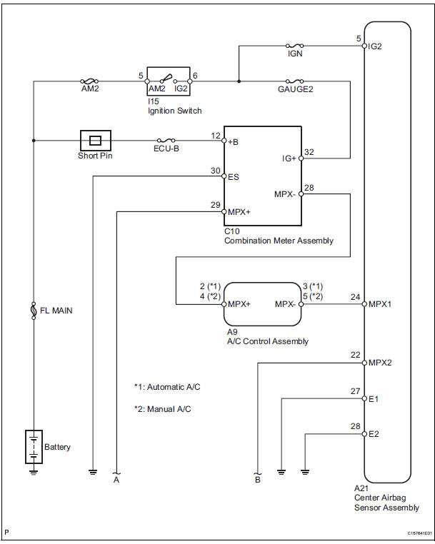
The signal to illuminate the SRS warning light is transmitted from the center airbag sensor assembly to the combination meter assembly through the multiplex communication system.
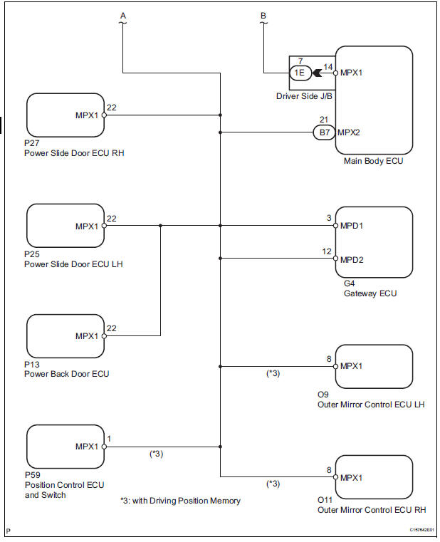
WIRING DIAGRAM
INSPECTION PROCEDURE
1 CHECK MULTIPLEX COMMUNICATION SYS
- Check if the multiplex communication DTC is output.
HINT: The center airbag sensor assembly of this system is connected to the multiplex communication system.
Therefore, before starting troubleshooting, make sure to check that there is no trouble in the multiplex communication system.
OK: The Multiplex communication system DTC is not output
2 CHECK BATTERY
- Measure the voltage of the battery.
Standard voltage: 11 to 14 V
3 CHECK CONNECTORS
- Turn the ignition switch to the LOCK position.
- Disconnect the negative (-) terminal cable from the battery, and wait for at least 90 seconds.
- Check that the connectors are properly connected to the center airbag sensor assembly and combination meter assembly.
OK: The connectors are properly connected.
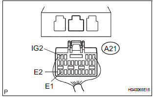
4 CHECK WIRE HARNESS (SOURCE VOLTAGE OF CENTER AIRBAG SENSOR ASSEMBLY)
- Disconnect the connectors from the center airbag sensor assembly.
- Connect the negative (-) terminal cable to the battery, and wait for at least 2 seconds.
- Turn the ignition switch to the ON position.
- Operate all components of the electrical system (defogger, wipers, headlight, heater blower, etc.).
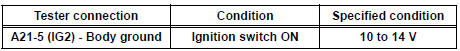
- Measure the voltage according to the value(s) in the table below.
Standard voltage
- Turn the ignition switch to the LOCK position.
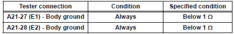
- Measure the resistance according to the value(s) in the table below.
Standard resistance
5 CHECK WIRE HARNESS (SOURCE VOLTAGE OF COMBINATION METER ASSEMBLY)
- Disconnect the negative (-) terminal cable from the battery, and wait for at least 90 seconds.
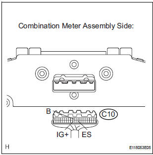
- Disconnect the connector from the combination meter assembly.
- Connect the negative (-) terminal cable to the battery, and wait for at least 2 seconds.
- Turn the ignition switch to the ON position.
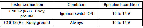
- Measure the voltage according to the value(s) in the table below.
Standard voltage
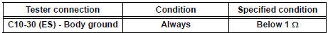
- Turn the ignition switch to the LOCK position.
- Measure the resistance according to the value(s) in the table below.
Standard resistance
6 CHECK SRS WARNING LIGHT
- Turn the ignition switch to the LOCK position.
- Disconnect the negative (-) terminal cable from the battery, and wait for at least 90 seconds.
- Connect the connector to the combination meter assembly.
- Connect the negative (-) terminal cable to the battery, and wait for at least 2 seconds.
- Turn the ignition switch to the ON position.
- Check the SRS warning light condition.
OK: After the primary check period, SRS warning light goes off for approximately 10 seconds, and remains on.
HINT: The primary check period shows approximately 6 seconds after the ignition switch is turned to the ON position.
REPLACE CENTER AIRBAG SENSOR ASSEMBLY
 Short to B+ in Rear Curtain Shield Squib LH
Circuit
Short to B+ in Rear Curtain Shield Squib LH
Circuit
DTC B1638/86 Short to B+ in Rear Curtain Shield Squib LH
Circuit
DESCRIPTION
The rear curtain shield squib LH circuit consists of the center airbag sensor
assembly and the curtain
shield airbag ...
 SRS Warning Light does not Come ON
DESCRIPTION
WIRING DIAGRAM
INSPECTION PROCEDURE
1 CHECK BATTERY
Measure the voltage of the battery.
Standard voltage:
11 to 14 V
2 CHECK CONNECTORS
Turn the ignition switch to the LOCK ...
Other materials:
Disassembly
1. REMOVE NO. 2 FRONT AXLE INBOARD JOINT BOOT LH CLAMP
(a) Using pliers, remove the No. 2 front axle inboard
joint boot LH clamp, as shown in the illustration.
2. REMOVE FRONT AXLE INBOARD JOINT BOOT LH
CLAMP
(a) Remove the front axle inboard joint boot LH clamp
using the same procedures a ...
Short to GND in Side Squib LH Circuit
DTC B0117/45 Short to GND in Side Squib LH Circuit
DESCRIPTION
The side squib LH circuit consists of the center airbag sensor assembly and
the front seat side airbag
assembly LH.
This circuit instructs the SRS to deploy when deployment conditions are met.
DTC B0117/45 is recorded when a s ...
Installation
1. INSTALL FRONT SHOULDER BELT ANCHOR
ADJUSTER ASSEMBLY
Install the front shoulder belt anchor adjuster
assembly with the bolt.
Torque: 42 N*m (430 kgf*cm, 31 ft.*lbf)
2. INSTALL CENTER PILLAR UPPER GARNISH
3. INSTALL FRONT SEAT OUTER BELT ASSEMBLY
NOTICE:
Do not disassemble ...
