Toyota Sienna Service Manual: Starting system
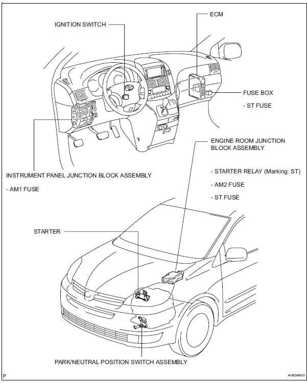
Parts location
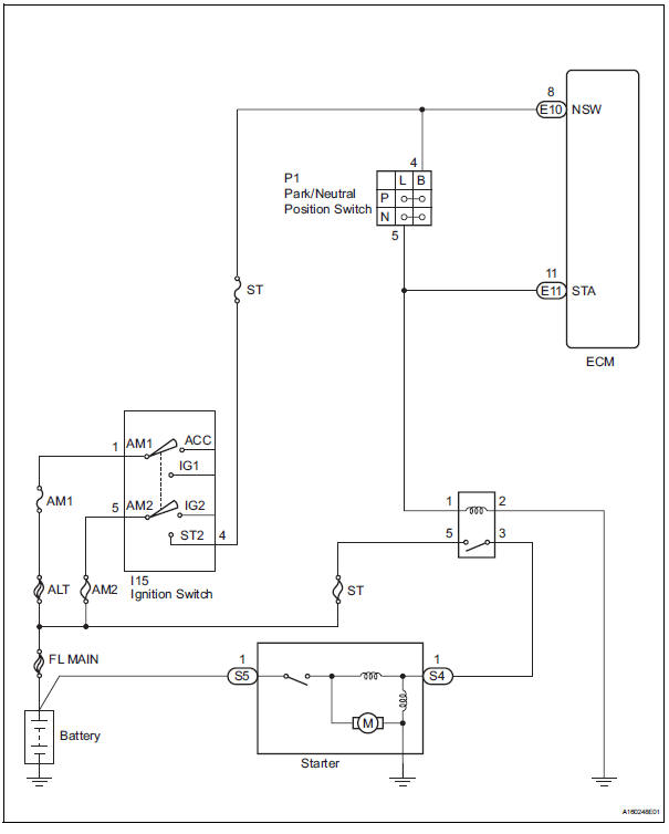
System diagram
The starting system rotates the starter motor according to the signals from the ignition switch and pnp switch.
 2Gr-fe starting
...
 Starter
Components
...
Other materials:
Removal
1. REMOVE FRONT EXHAUST PIPE ASSEMBLY
HINT:
(See page EX-8)
2. REMOVE PROPELLER WITH CENTER BEARING
SHAFT ASSEMBLY
HINT:
(See page PR-3)
3. REMOVE REAR DIFFERENTIAL FILLER PLUG
(a) Using a hexagon wrench (10 mm), remove the filler
plug and gasket.
4. REMOVE REAR DIFFERENTIAL DRAIN PLUG
(a ...
Slide Door Closer RH does not Operate
DESCRIPTION
The slide door ECU RH controls the slide door closer. In response to the
signals output from the switches
in the slide door lock, the slide door closer drives the closer motor.
HINT:
The slide door closer system operates regardless of the power slide door main
switch ON / OFF.
W ...
Sliding doors
Vehicles without power sliding doors
The sliding doors can be opened and closed using the sliding
door handle. The sliding door can be locked and unlocked using
the wireless remote control, door lock switch or inside lock
knob.
Vehicles with power sliding doors
...
