Toyota Sienna Service Manual: Steering Angle Sensor Zero Point Malfunction
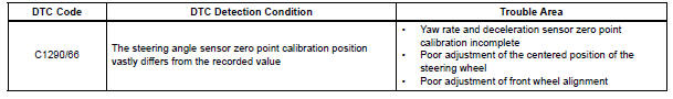
DTC C1290/66 Steering Angle Sensor Zero Point Malfunction
DESCRIPTION
The skid control ECU acquires steering angle sensor zero point every time the ignition switch is turned to the ON position and the vehicle is driven at 35 km/h (22 mph) or more for approximately 5 seconds. The ECU also stores the previous zero point.
If front wheel alignment or steering wheel position is adjusted without disconnecting the negative battery terminal, or if yaw rate and deceleration sensor zero point is not acquired after the adjustments have been completed, the skid control ECU detects the difference between the previous zero point and newly acquired zero point and outputs this DTC to indicate a poor adjustment.
Warning of the steering angle sensor zero point malfunction will be cancelled by turning the ignition switch off.
INSPECTION PROCEDURE
NOTICE: When replacing the brake actuator assembly, perform zero point calibration (See page BC-70).
1 PERFORM ZERO POINT CALIBRATION OF YAW RATE AND DECELERATION SENSOR
(a) Perform zero point calibration of the yaw rate and deceleration sensor (See page BC-70).
HINT:
- When the stored zero point of the yaw rate and deceleration sensor is erased, steering angle sensor zero point will also be erased.
- If the zero point and output value of the yaw rate and deceleration sensor and the output value of the speed sensors are not normal, steering angle sensor zero point cannot be acquired normally even if the vehicle is driven straight ahead at 35 km/h (22 mph) or more.

2 CHECK STEERING ANGLE SENSOR ZERO POINT CALIBRATION
(a) Drive the vehicle straight ahead at 35 km/h (22 mph) or more for at least 5 seconds.
(b) Check that the centered position of the steering wheel is correctly set while driving straight ahead.
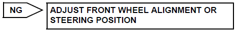
HINT: If front wheel alignment and steering position are adjusted as a result of abnormal centered position of the steering wheel, acquire yaw rate and deceleration sensor zero point again after the adjustments are completed.
OK: The centered position of the steering wheel is correctly set.

3 RECONFIRM DTC
(a) Turn the ignition switch off.
(b) Clear the DTC (See page BC-82).
(c) Start the engine.
(d) Drive the vehicle and turn the steering wheel to the right and left at the speed of 35 km/h (22 mph) or more.
(e) Check if the same DTC is recorded (See page BC-82).
Result 


END
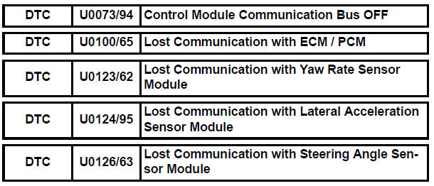
Control Module Communication Bus OFF
INSPECTION PROCEDURE
Refer to CAN communication system (See page CA-7).
 Open in Pump Motor Circuit
DTC C1251/51 Open in Pump Motor Circuit
DESCRIPTION
WIRING DIAGRAM
INSPECTION PROCEDURE
1 PERFORM ACTIVE TEST USING INTELLIGENT TESTER (ABS MOTOR RELAY)
(a) Connect the intelligent tester ...
 ABS Warning Light Remains ON
DESCRIPTION
If any of the following is detected, the ABS warning light remains on.
The skid control ECU connectors are disconnected from the skid control
ECU.
There is a malfunction in the s ...
Other materials:
Radio and Navigation Assembly Communication Error
INSPECTION PROCEDURE
1 IDENTIFY THE COMPONENT SHOWN BY THE SUB-CODE
Enter the diagnostic mode.
Press the "LAN Mon" switch to change to "LAN Monitor"
mode.
Identify the component shown by the sub-code.
HINT:
"110 (multi-display)" i ...
Operation check
1. NOTICE WHEN CHECKING THE FOLLOWING
Power door lock/unlock function:
The wireless door lock control function operates
only when the following 3 conditions are met:
No key is inserted in the ignition key cylinder.
All the doors are closed.
The power door lock sys ...
Problem symptoms table
HINT:
Before inspecting the suspected areas listed in the table
below, check the fuse and relay.
Before inspecting the suspected areas listed in the table
below, check the DTCs.
Methods used to verify the cause of the problem are listed
in order of probability in the ...
