Toyota Sienna Service Manual: Steering pad switch
COMPONENTS
 Audio terminal
COMPONENTS
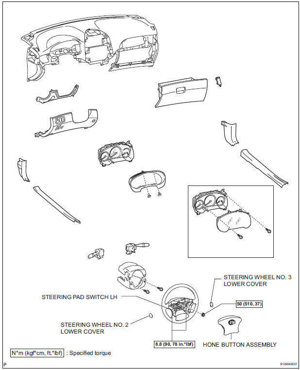
REMOVAL
1. REMOVE INSTRUMENT CLUSTER CENTER NO. 2 FINISH PANEL
Using a moulding remover, disengage the 3 clips.
Disconnect the connector and remove the
instrumen ...
 Removal
1. DISCONNECT CABLE FROM NEGATIVE BATTERY TERMINAL
2. REMOVE STEERING WHEEL NO. 2 LOWER COVER
3. REMOVE STEERING WHEEL NO. 3 LOWER COVER
4. REMOVE HONE BUTTON ASSEMBLY
5. REMOVE STEERING PAD SWITC ...
Other materials:
Assist grips
Type A
An assist grip installed on the ceiling
can be used to support your
body while sitting on the seat.
Type B
An assist grip installed on the pillar
can be used when getting in
or out of the vehicle and others.
WARNING
Type A: Do not use the assist grip when g ...
Black Screen
INSPECTION PROCEDURE
1 CHECK DISPLAY SETTING
Check that the display is not in "Screen OFF" mode.
OK:
The display setting is not in "Screen OFF" mode.
2 CHECK IMAGE QUALITY SETTING
Check that the screen color quality can be set.
OK:
Setting is possible.
PRESS PA ...
Detection range of the sensors
Approximately 2.0 ft. (60 cm)
Approximately 2.8 ft. (85 cm)
Approximately 5.9 ft. (180 cm)
The diagram shows the detection
range of the sensors. Note that the
sensors cannot detect obstacles
that are extremely close to the
vehicle.
The range of the sensors may
change depending ...
