Toyota Sienna Service Manual: Steering Pad Switch Circuit
DESCRIPTION
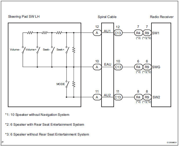
This circuit sends an operation signal from the steering pad switch to the radio receiver.
If there is an open in the circuit, the audio system cannot be operated using the steering pad switch.
If there is a short in the circuit, the same condition as that when the switch is continuously depressed occurs.
Therefore, the radio receiver cannot be operated using the steering pad switch, and also the radio receiver itself cannot function.
WIRING DIAGRAM
INSPECTION PROCEDURE
NOTICE: The vehicle is equipped with an SRS (Supplemental Restraint System) which includes components such as airbags. Before servicing (including removal or installation of parts), be sure to read the precautionary notice for the Supplemental Restraint System
1 INSPECT RADIO RECEIVER
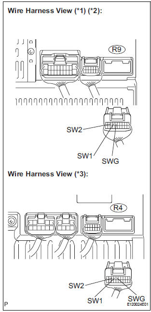
- Disconnect the radio receiver connector R4 or R9.
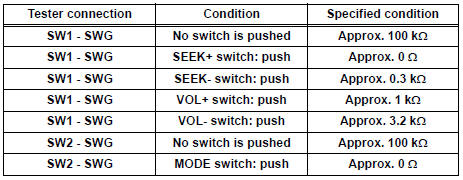
- Measure the resistance according to the value(s) in the table below.
Standard resistance
*1: 10 Speaker without Navigation System
*2: 6 Speaker with Rear Seat Entertainment System
*3: 6 Speaker without Rear Seat Entertainment System
PROCEED TO NEXT CIRCUIT INSPECTION SHOWN IN PROBLEM SYMPTOMS TABLE
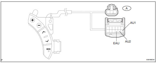
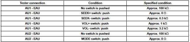
2 INSPECT STEERING PAD SWITCH ASSEMBLY
- Disconnect the steering pad switch LH connector.
- Measure the resistance according to the values in the table below.
Standard resistance
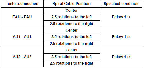
3 INSPECT SPIRAL CABLE
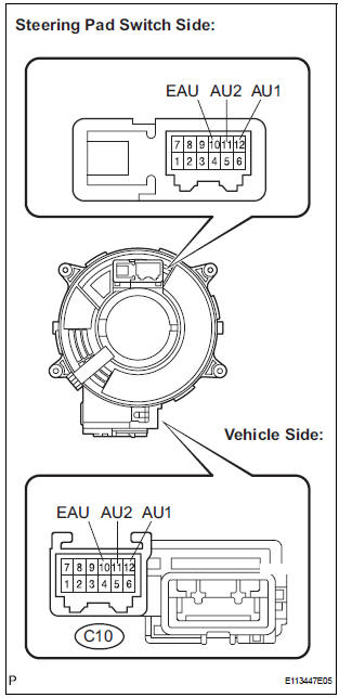
- Disconnect the steering pad switch and spiral cable connectors.
- Measure the resistance according to the value(s) in the table below.
Standard resistance
NOTICE: The spiral cable is an important part of the SRS airbag system. Incorrect removal or installation of the spiral cable may prevent the airbag from deploying. Be sure to read the page shown in the brackets
REPAIR OR REPLACE HARNESS OR CONNECTOR (SPIRAL CABLE - RADIO RECEIVER)
 Vehicle Speed Signal Circuit between Radio Receiver and Combination
Meter
Vehicle Speed Signal Circuit between Radio Receiver and Combination
Meter
DESCRIPTION
This circuit is necessary for the ASL (Auto Sound Leveliser) built into the
radio receiver.
Speed signals are received from the combination meter and used for the ASL.
The ASL fun ...
 Illumination Circuit
DESCRIPTION
Power is supplied to the radio receiver and steering pad switch illumination
when the light control switch is
in the TAIL or HEAD position.
WIRING DIAGRAM
INSPECTION PROCEDURE
N ...
Other materials:
Center Airbag Sensor Assembly Malfunction
DTC B1100/31 Center Airbag Sensor Assembly Malfunction
DESCRIPTION
The center airbag sensor assembly consists of the center airbag sensor
assembly, safing sensor, drive
circuit, diagnosis circuit and ignition control, etc.
It receives signals from the airbag sensor, judges whether or not the ...
Inspection
1. INSPECT SEAT HEATER SWITCH LH
Measure the resistance of the seat heater switch
when the switch is operated.
Resistance
If the result is not as specified, replace the switch.
HINT:
As the dial is being turned, the resistance changes
gradually.
Push the seat h ...
Removal
1. DRAIN BRAKE FLUID
NOTICE:
Wash brake fluid off immediately if it adheres to any
painted surface.
2. DISCONNECT BATTERY NEGATIVE TERMINAL
3. REMOVE AIR CLEANER ASSEMBLY WITH HOSE
4. REMOVE BRAKE ACTUATOR WITH BRACKET
(a) Release the latch of the brake actuator connector to
disconnect the c ...
