Toyota Sienna Service Manual: Stereo component amplifier
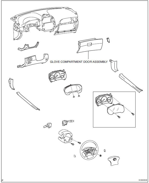
COMPONENTS
Removal
1. REMOVE GLOVE COMPARTMENT DOOR ASSEMBLY
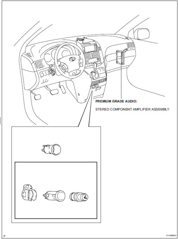
2. REMOVE STEREO COMPONENT AMPLIFIER ASSEMBLY

- Disconnect the connectors.
- Remove the 2 nuts and the stereo component amplifier assembly.
Installation
1. INSTALL STEREO COMPONENT AMPLIFIER ASSEMBLY
- Install the stereo component amplifier assembly with the 2 nuts.
- Connect the connectors.
2. INSTALL GLOVE COMPARTMENT DOOR ASSEMBLY
 Installation
1. INSTALL RADIO NO. 2 BRACKET
Install radio No. 2 bracket with the 4 screws.
2. INSTALL RADIO NO. 1 BRACKET
Install radio No. 1 bracket with the 4 screws.
3. INSTALL R ...
 Television display
COMPONENTS
Removal
1. REMOVE TELEVISION BASE
Release the 4 clips and remove the television base.
2. REMOVE TELEVISION DISPLAY ASSEMBLY
Disconnect the connector and r ...
Other materials:
Short to GND in CAN Bus Line
DESCRIPTION
A short to GND is suspected in the CAN bus wire when the resistance between
terminals 4 (CG) and 6
(CANH), or terminals 4 (CG) and 14 (CANL) of the DLC3 is below 200 Ω.
Symptoms
Trouble Area
The resistance between terminals 6 (CANH) and 4 (CG), or ter ...
Removal
1. REMOVE FRONT WHEEL
2. REMOVE REAR WHEEL
3. REMOVE TIRE PRESSURE WARNING VALVE AND TRANSMITTER
(a) Remove the valve core and cap, and release the air
from the tire.
(b) After ensuring that a sufficient amount of air has
been released, remove the nut and washer that are
used to secure ...
Front Occupant Classification Sensor RH Circuit
Malfunction
DTC B1781 Front Occupant Classification Sensor RH Circuit
Malfunction
DESCRIPTION
The front occupant classification sensor RH circuit consists of the occupant
classification ECU and the
front occupant classification sensor RH.
DTC B1781 is recorded when a malfunction is detected in the fron ...
