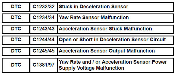
Toyota Sienna Service Manual: Stuck in Deceleration Sensor
DESCRIPTION
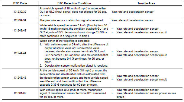
The yaw rate sensor and deceleration sensor signal is sent to the skid control ECU through the CAN communication system. When there is a malfunction in the communication, it will be detected by the diagnosis function.
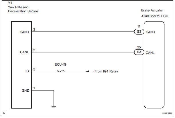
WIRING DIAGRAM
INSPECTION PROCEDURE
HINT: When U0073/94, U0100/65, U0123/62, U0124/95 or U0126/63 are output accompanied with C1232/32, C1234/34, C1243/43, C1244/44, C1245/45 or C1381/97, inspect and repair the trouble areas indicated by U0073/94, U0100/65, U0123/62, U0124/95 or U0126/63 first.
1 CHECK YAW RATE AND DECELERATION SENSOR INSTALLATION
(a) Check that the yaw rate and deceleration sensor has been installed properly (See page BC-197).
OK: The sensor should be tightened to the specified torque.
The sensor should not be tilted.

2 INSPECT YAW RATE AND DECELERATION SENSOR (IG TERMINAL)
(a) Disconnect the yaw rate and deceleration sensor connector.
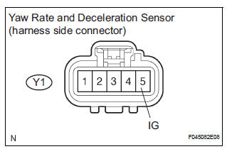
(b) Turn the ignition switch to the ON position.
(c) Measure the voltage according to the value(s) in the table below.
Standard voltage 

3 INSPECT YAW RATE AND DECELERATION SENSOR (GND TERMINAL)
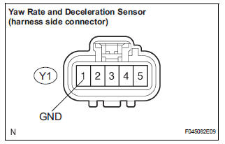
(a) Disconnect the yaw rate and deceleration sensor connector.
(b) Measure the resistance according to the value(s) in the table below.
Standard resistance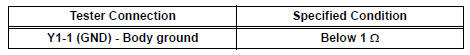

REPLACE YAW RATE AND DECELERATION SENSOR
 Steering Angle Sensor Circuit Malfunction
DTC C1231/31 Steering Angle Sensor Circuit Malfunction
DESCRIPTION
The steering angle sensor signal is sent to the skid control ECU through the
CAN communication system.
When there is a malfunc ...
 Low Battery Positive Voltage
DTC C1241/41 Low Battery Positive Voltage
DESCRIPTION
WIRING DIAGRAM
INSPECTION PROCEDURE
1 INSPECT ECU-IG FUSE
(a) Remove the ECU-IG fuse from the driver side J/B.
(b) Check continu ...
Other materials:
Removal
1. PRECAUTION
CAUTION:
Be sure to read "PRECAUTION" thoroughly before
servicing.
2. DISCONNECT CABLE FROM NEGATIVE BATTERY
TERMINAL
CAUTION:
Wait for 90 seconds after disconnecting the cable to
prevent the airbag working.
3. REMOVE FRONT SEAT ASSEMBLY (for Manual Seat)
4. REMOVE ...
Playing an audio CD and
MP3/WMA/AAC discs
Insert disc or select “CD” on the audio source selection screen
with a disc inserted to begin listening to a CD.
Audio control screen
Pressing the “AUDIO” button displays the audio control screen from
any screens of the selected source.
Audio source selection screen
appears
D ...
Front Occupant Classification Sensor RH Circuit
Malfunction
DTC B1781 Front Occupant Classification Sensor RH Circuit
Malfunction
DESCRIPTION
The front occupant classification sensor RH circuit consists of the occupant
classification ECU and the
front occupant classification sensor RH.
DTC B1781 is recorded when a malfunction is detected in the fron ...
