Toyota Sienna 2010-2026 Owners Manual: Sun visors
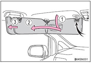
- To set the visor in the forward position, flip it down.
- To set the visor in the side position, flip down, unhook, and swing it to the side.
- To use the side extender, place the visor in the side position, then slide it backward.

 Vanity mirrors
Open the cover.
The light turns on when the cover
is opened
To prevent battery discharge
If the vanity lights remain on for 20 minutes while the engine is off, the
lights
will turn off auto ...
Other materials:
Installation
1. Install transmission valve body assembly
(a) Install the shift solenoid valve SL1 to the valve body
assembly with the bolt.
Torque: 6.6 N*m (67 kgf*cm, 58 in.*lbf)
(b) Install the shift solenoid valve SL2 to the valve body
assembly with the bolt.
Torque: 11 N*m (110 kgf*cm, 8 ft ...
Rear view monitor
system
The rear view monitor system assists the driver by displaying an
image of the view behind the vehicle and guide lines while backing
up, for example while parking.
The screen illustrations used in this text are intended as examples,
and may differ from the image that is actually displayed on the
...
Display does not Dim when Light Control Switch is Turned ON
INSPECTION PROCEDURE
1 CHECK IMAGE QUALITY SETTING
Enter the display adjustment screen by pressing the
"DISPLAY" switch.
Turn the light control switch to the TAIL position.
Check if "DAY MODE" on the display adjustment is ON.
OK:
"DAY MODE" ...
