Toyota Sienna Service Manual: System description
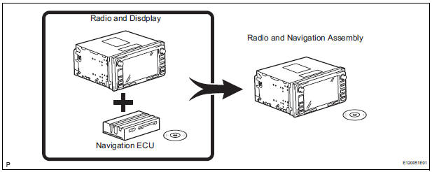
1. Radio and navigation assembly outline
- Conventionally, 2 separate devices, a "radio and display" and a "navigation ECU" are used. This model has adopted a new type, combining these devices into a single unit.
2. Navigation system outline
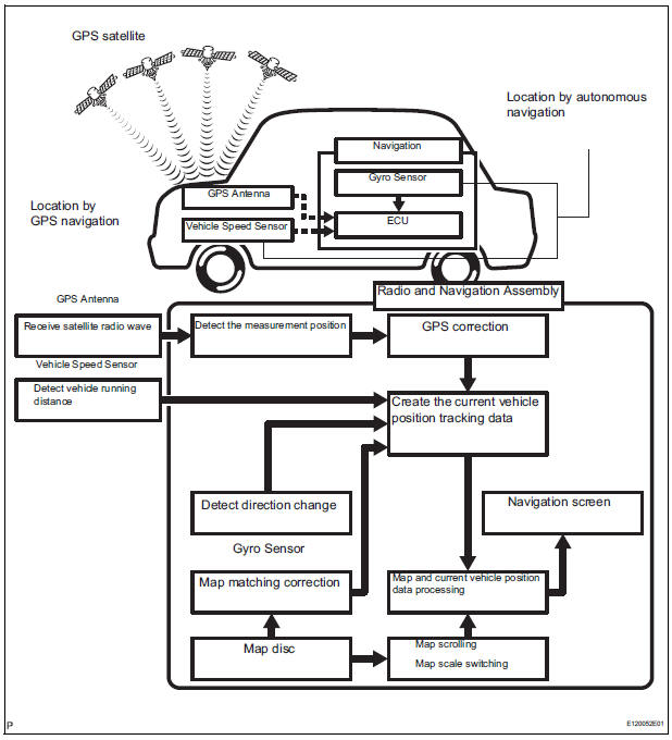
- Vehicle position tracking methods
It is essential that the navigation system correctly tracks the current vehicle position and displays it on the map. There are 2 methods to track the current vehicle position: autonomous (dead reckoning) and GPS* (satellite) navigation. Both navigation methods are used in conjunction with each other.*GPS (Global Positioning System)
|
Operation |
Description |
| Vehicle Position Calculation | The radio and navigation assembly calculates the current vehicle position (direction and current position) using the direction deviation signal from the gyro sensor and the running distance signal from the vehicle speed sensor and creates the driving route. |
| Map Display Processing | The radio and navigation assembly displays the vehicle track on the map by processing the vehicle position data, vehicle running track, and map data from the map disc |
| Map Matching | The map data from the map disc is compared to the vehicle position and running track data. Then, the vehicle position is matched with the nearest road. |
| GPS Correction | The vehicle position is matched to the position measured by GPS.
Then, the measurement position data from the GPS unit is compared with the vehicle position and running track data. If the position is widely different, the GPS measurement position is used. |
| Distance Correction | The running distance signal from the vehicle speed sensor includes the error caused by tire wear and slippage between the tires and road surface. Distance correction is performed to account for this. The radio and navigation assembly automatically offsets the running distance signal to make up for the difference between it and the distance data of the map. The offset is automatically updated. |

HINT: The combination of autonomous and GPS navigation makes it possible to display the vehicle position even when the vehicle is in places where the GPS radio wave cannot receive a signal. When only autonomous navigation is used, however, the mapping accuracy may slightly decline.
- Autonomous navigation
This method determines the relative vehicle position based on the running track determined by the gyro and vehicle speed sensors located in the radio and navigation assembly.
- Gyro sensor
Calculates the direction by detecting angular velocity. It is located in the radio and navigation assembly. - Vehicle speed sensor
Used to calculate the vehicle running distance.
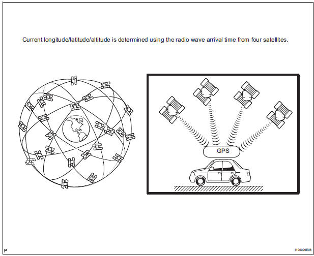
- GPS navigation (Satellite navigation)
This method detects the absolute vehicle position using radio waves from a GPS satellite.* GPS satellites were launched by the U.S.
Department of Defence for military purposes.
|
Number of satellites |
Measurement |
Description |
| 2 or less | Measurement impossible | Vehicle position cannot be obtained because the number of satellites is not enough. |
| 3 | 2-dimensional measurement is possible | Vehicle position is obtained based on the current longitude and latitude. (This is less precise than 3-dimensional measurement.) |
| 4 | 3-dimensional measurement is possible | Vehicle position is obtained based on the current longitude, latitude and altitude. |
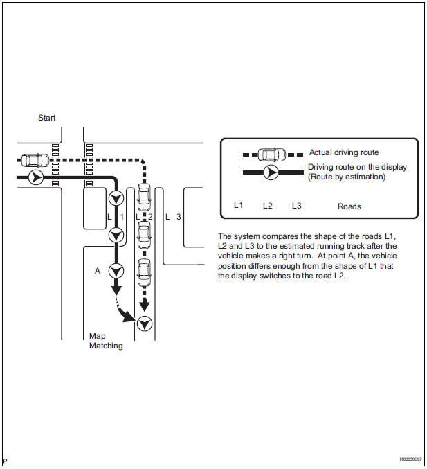
- Map matching
The current driving route is calculated by autonomous navigation (according to the gyro sensor and vehicle speed sensor) and GPS navigation. This information is then compared with possible road shapes from the map data in the map disc and the vehicle position is set onto the most appropriate road.
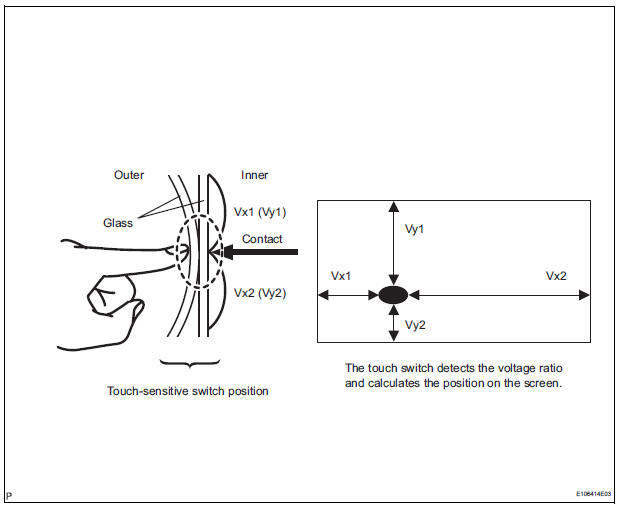
- Touch switch
Touch switches are touch-sensitive (interactive) switches operated by touching the screen. When a switch is pressed, the outer glass bends in to contact the inner glass at the pressed position. By doing this, the voltage ratio is measured and the pressed position is detected.
3. DVD (Digital Versatile Disc) player outline (for navigation map)
- The radio and navigation assembly (built-in navigation ECU) uses a laser pickup to read the digital signals recorded on a DVD.
HINT:
- Do not disassemble any part of the radio and navigation assembly (built-in navigation ECU).
- Do not apply oil to the radio and navigation assembly (built-in navigation ECU).
- Do not insert anything but a DVD into the radio and navigation assembly (built-in navigation ECU).
CAUTION: Do not look directly at the laser pickup because the radio and navigation assembly (built-in navigation ECU) uses an invisible laser beam.
Be sure to only operate the navigation system as instructed.
4. CD (Compact Disc) player outline
- A compact disc player uses a laser pickup to read digital signals recorded on a compact disc (CD). By converting the digital signals to analog, it can play music and other things.
NOTICE:
- Do not disassemble any part of the CD player.
- Do not apply oil to the CD player.
- Do not insert anything but a CD into the CD player.
CAUTION: Do not look directly at the laser pickup because the CD player uses an invisible laser beam. Be sure to only operate the player as instructed.
- Usable discs
- This player can only play audio CDs, CD-Rs (CD-Recordable), and CD-RWs (CDReWritable) that have any of the following marks:
- Precautions for use of discs
NOTICE:
- Copy-protected CDs cannot be played.
- CD-Rs and CD-RWs may not be played depending on the recording conditions or characteristics of the discs, or due to damage, dirt, or deterioration caused by leaving the discs in the cabin for a long time.
- Unfinalized CD-Rs and CD-RWs cannot be played.
- Dualdiscs that mate DVD recorded material on one side with CD digital audio material on the other cannot be played.
- Keep the discs away from dirt. Be careful not to damage the discs or leave your fingerprints on them.
- Hold discs by the outer edge and center hole with the label side up.
- Leaving the disc exposed halfway out of the slot for a long time after pressing the disc eject button may cause deformation of the disc, making the disc unusable.
- If discs have adhesive tape, stickers, CDR labels, or any traces of such labels attached, the discs may not be ejected or player malfunctions may result.
- Keep the discs away from direct sunlight.
(Exposure to direct sunlight may cause deformation of the disc, making the disc unusable.)
- Do not use odd-shaped CDs because these may cause player malfunctions.
- Do not use discs whose recording portion is transparent or translucent because they may not be inserted, ejected, or played normally.
HINT:
- When it is cold or it is raining, if the windows mist up, mist and also dew may form in the player. In such a case, the CD may skip or the CD may stop in the middle of play. Ventilate or dehumidify the cabin for a while before using the player.
- The CD may skip if the player experiences strong vibrations when the vehicle is driven on rough road or similar uneven surface(s).
- Cleaning
NOTICE: Do not use a lens cleaner because it may cause a malfunction in the pickup portion of the player.
- If dirt is on the disc surface, wipe it clean with a soft dry cloth such as an eyeglass cleaner for plastic lenses from the inside to the outside in a radial direction.
NOTICE:
- Pressing on the disc by hand or rubbing the disc with a hard cloth may scratch the disc surface.
- Use of solvent such as a record spray, antistatic agent, alcohol, benzine, and thinner, or a chemical cloth may cause damage to the disc, making the disc unusable.
5. MP3 / WMA OUTLINE
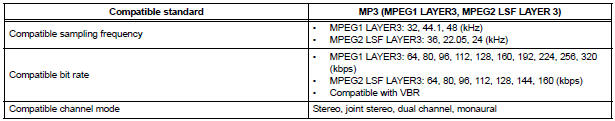
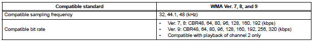
- Playable MP3 file standards
- Playable WMA file standards
- ID3 tag and WMA tag
- Additional textual information called ID3 tag can
be input to MP3 files. Information such as song
titles and artist names can be stored.
HINT: This player is compatible with the ID3 tags of ID3 Ver. 1.0 and 1.1, and ID3 Ver. 2.2 and 2.3.
(Number of characters complies with ID3 Ver.
1.0 and 1.1.)
- Additional textual information called WMA tag can be input to WMA files. Information such as song titles and artist names can be stored.
- Usable media
- Only CD-ROMs, CD-Rs (CD-Recordable), and CD-RWs (CD-ReWritable) only can be used to play MP3/WMA files.
NOTICE:
- CD-Rs and CD-RWs are more easily affected by a hot and humid environment than discs used for normal audio CDs. For this reason, some CD-Rs and CD-RWs may not be played.
- If there are fingerprints or scratches on the disc, the disc may not be played or the CD may skip.
- Some CD-Rs and CD-RWs deteriorate if they are left in the cabin for a long time.
- Keep CD-Rs and CD-RWs in a storage case that is impenetrable to light.
- Usable media format
- Usable media format

HINT:
- As for MP3/WMA files written in any format other than those above, the contents of the files may not be played normally or the file names or folder names may not be displayed correctly.
- This player is compatible with multi-session discs and can play CD-Rs and CD-RWs on which MP3/WMA files are added. However, only the first session can be played.
- Discs whose first session includes both music data and MP3 or WMA format data cannot be played.
- Standard and restrictions
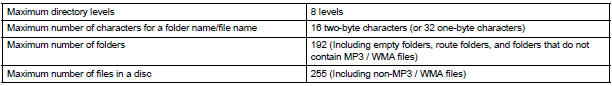
- File names
- Only files with an extension of ".mp3" or ".wma" can be recognized and played as MP3 or WMA files.
- Save MP3 or WMA files with an extension of ".mp3" or ".wma".
NOTICE: If saving non-MP3 or non-WMA files with an extension of ".mp3" or ".wma", those files are wrongly recognized as MP3 orWMA files and played. A loud noise may occur and damage to the speaker may result.
6. AVC-LAN Description
- What is AVC-LAN? AVC-LAN, an abbreviation for "Audio Visual Communication Local Area Network", is a united standard developed by the manufacturers in affiliation with Toyota Motor Corporation. This standard pertains to audio and visual signals as well as switch and communication signals.
- Purpose: Recently, car audio systems have rapidly developed and the functions have vastly changed. The conventional car audio system is being integrated with multi-media interfaces similar to those in navigation systems. At the same time, customers are demanding higher quality from their audio systems. This is merely an overview of the standardization background. The specific purposes are as follows:
- To solve sound problems, etc. caused by using components of different manufacturers through signal standardization.
- To allow each manufacturer to concentrate on developing products they do best. From this, reasonably priced products can be produced.
HINT:
- If a short to +B or short to ground is detected in the AVC-LAN circuit, communication is interrupted and the audio system will stop functioning.
- If an audio system is equipped with a
navigation system, the multi-display unit acts
as the master unit.
If the navigation system is not equipped, the audio head unit acts as the master unit instead. If the radio and navigation assembly is equipped, it is the master unit.
- The radio and navigation assembly contains a resistor that is necessary to enable communication on the different AVC-LAN circuits.
- The car audio system with an AVC-LAN circuit has a diagnostic function.
- Each component has a specified number (3- digit) called a physical address. Each function has a number (2-digit) called a logical address.
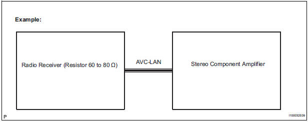
7. Communication system outline
- Components of the navigation system communicate with each other via the AVC-LAN.
- The radio and navigation assembly has enough resistance (60 to 80 Ω) necessary for communication.
- If a short circuit or open circuit occurs in the AVCLAN circuit, communication is interrupted and the navigation system will stop functioning.
8. Diagnostic function outline
- The audio system has a diagnostic function (the result is indicated on the master unit).
- A 3-digit hexadecimal component code (physical address) is allocated to each component on the AVC-LAN. Using this code, the component in the diagnostic function can be displayed.
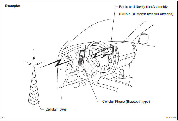
9. Bluetooth outline

- Bluethooth is a trademark owned by Bluetooth SIG.
Inc.
- Bluetooth is a new wireless connection technology
that uses the 2.4 GHz frequency band. This makes
it possible to connect a cellular phone (Bluetooth
compatible phone *1) to the radio and navigation
assembly (the Bluetooth system is built in), and use
the handsfree function of the cellular phone, even if
it is in a pocket or bag. As a result, it is not
necessary to use a connector attached directly to
the cellular phone.
*1: Some versions of Bluetooth compatible cellular phones may not function.
HINT: The communication performance of Bluetooth may vary depending on obstructions or radio wave conditions between communication devices, electromagnetic radiation, communication device sensitivity, or antenna capacity.
 Navigation system
PARTS LOCATION
SYSTEM DIAGRAM
...
 How to proceed with
troubleshooting
How to proceed with
troubleshooting
1 VEHICLE BROUGHT INTO A WORKSHOP
2 DIAGNOSTIC QUESTIONING AND SYMPTOM CONFIRMATION
Ask the customer about symptoms and confirm
malfunctions.
3 CONFIRM THE SYSTEM NORMAL CONDITION
4 CHECK D ...
Other materials:
Light Control Switch Circuit
DESCRIPTION
This circuit detects the state of the headlight dimmer switch.
WIRING DIAGRAM
INSPECTION PROCEDURE
1 READ VALUE OF INTELLIGENT TESTER
Connect the intelligent tester to DLC3.
Turn the ignition switch ON and push the intelligent
tester main switch ON.
Select t ...
Intake Air Temperature Circuit
DESCRIPTION
The Intake Air Temperature (IAT) sensor, mounted on the Mass Air Flow (MAF)
meter, monitors the IAT.
The IAT sensor has a built-in thermistor with a resistance that varies according
to the temperature of the
intake air. When the IAT is low, the resistance of the thermistor i ...
Occupant Classification System Malfunction
DTC B1150/23 Occupant Classification System Malfunction
DESCRIPTION
The occupant classification system circuit consists of the center airbag
sensor assembly and the occupant
classification ECU.
If the center airbag sensor assembly receives signals from the occupant
classification ECU, it d ...
