Toyota Sienna Service Manual: System description
1. MULTIPLEX COMMUNICATION SYSTEM (BEAN)
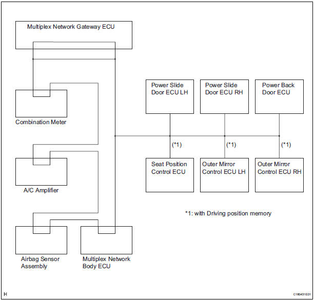
- The BEAN communication line is used to control the combination meter, the A/C amplifier, the airbag sensor assembly, the multiplex network body ECU, the power slide door ECU LH, the power slide door ECU RH, the power back door ECU, the seat position control ECU, the outer mirror control ECU LH, and the outer mirror ECU RH. If there is a shortcircuit (bus-down) in the line, the communication to the system that has a short-circuit (bus-down) will be disabled and the DTC concerning the system will be output from the multiplex network gateway ECU.
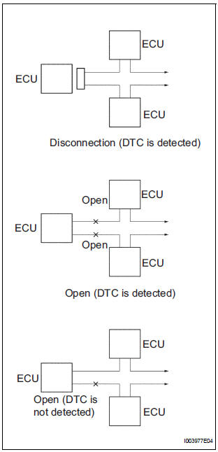
- If the DTC of ECU communication stop is output, connectors may be disconnected, or communication buses may be open at 2 points. It will not become abnormal with only 1 communication bus open.
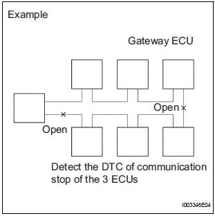
- If 2 communication buses are open at the points shown in the illustration, the DTC of ECU communication stop between those 2 buses is output.
2. CHECK COMMUNICATION FUNCTION
- Check the battery voltage.
Standard voltage: 11 to 14 V
- Inspect the DTC output.
- Check a DTC concerning the multiplex network body ECU by connecting the intelligent tester to the DLC3 and turning the ignition switch to the ON position.
- When the display shows DTCs concerning the ECU unconnected and the communication bus defective, perform the inspection depending on the troubleshooting procedures.
HINT: When another DTC is output, refer to the DTC table and check the applicable section.
 Multiplex communication system
PARTS LOCATION
...
 How to proceed with
troubleshooting
How to proceed with
troubleshooting
HINT:
Troubleshoot in accordance with the procedures on the
following pages.
1 VEHICLE BROUGHT TO WORKSHOP
2 DTC CHECK
Check for DTCs and make a note of the code that is
output (See page MP- ...
Other materials:
Oxygen (A/F) Sensor Heater Control Circuit
HINT
Although the DTC titles say the oxygen sensor, these DTCs relate to the
Air-Fuel Ratio (A/F) sensor.
Sensor 1 refers to the sensor mounted in front of the Three-Way
Catalytic Converter (TWC) and
located near the engine assembly.
DESCRIPTION
Refer to DTC P2195 (See page ES- ...
Display contents
The multi-information display presents
the driver with a variety of
vehicle data.
Menu icons
Displays the following information when an icon is selected.
Some of the information may be displayed automatically depending
on the situation.
Drive information
Select to display various ...
Installation
1. Install transmission valve body assembly
(a) Install the shift solenoid valve SL1 to the valve body
assembly with the bolt.
Torque: 6.6 N*m (67 kgf*cm, 58 in.*lbf)
(b) Install the shift solenoid valve SL2 to the valve body
assembly with the bolt.
Torque: 11 N*m (110 kgf*cm, 8 ft ...
