Toyota Sienna Service Manual: TC and CG Terminal Circuit
DESCRIPTION
DTC output mode is set by connecting terminals 13 (TC) and 4 (CG) of the DLC3. The DTCs are indicated by blinks of the tire pressure warning light.
WIRING DIAGRAM
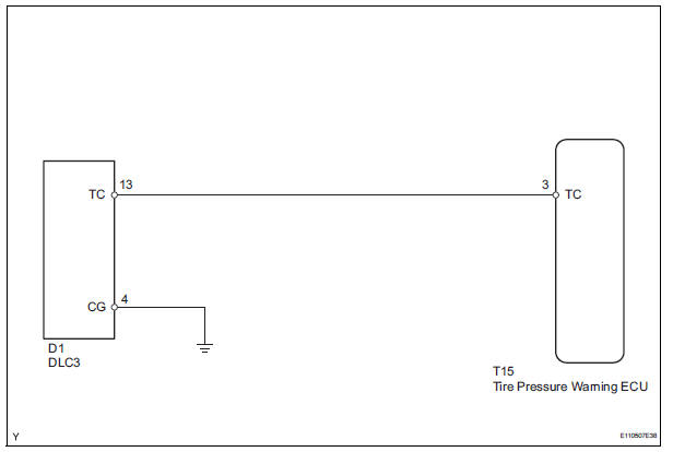
HINT: When each warning light blinks continuously, a ground short in the wiring of terminal TC of the DLC3 or an internal ground short in an ECU connected to this circuit may have occurred.
INSPECTION PROCEDURE
NOTICE: When replacing the tire pressure warning ECU, read the transmitter IDs stored in the old ECU using the intelligent tester and write them down before removal.
It is necessary to register an ID code after replacing the tire pressure warning valve and transmitter and/or the tire pressure warning ECU (See page TW-20).
1 CHECK HARNESS AND CONNECTOR (DLC3 - TIRE PRESSURE WARNING ECU)
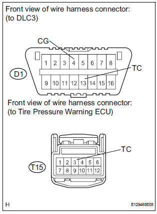
(a) Disconnect the T15 ECU connector.
(b) Measure the resistance according to the value(s) in the table below.
Standard resistance 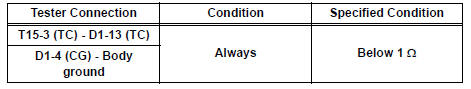

PROCEED TO NEXT CIRCUIT INSPECTION SHOWN IN PROBLEM SYMPTOMS TABLE (See page TW-28)
 ECU Power Source Circuit
DESCRIPTION
This is the power source for the tire pressure warning ECU.
WIRING DIAGRAM
INSPECTION PROCEDURE
NOTICE:
When replacing the tire pressure warning ECU, read the transmitter IDs
st ...
 Tire pressure warning receiver (w/ antenna)
Components
...
Other materials:
Short to B+ in Side Squib LH Circuit
DTC B0118/46 Short to B+ in Side Squib LH Circuit
DESCRIPTION
The side squib LH circuit consists of the center airbag sensor assembly and
the front seat side airbag
assembly LH (side squib LH).
This circuit instructs the SRS to deploy when deployment conditions are met.
DTC B0118/46 is re ...
Precaution
1. SRS AIRBAG SYSTEM HANDLING PRECAUTIONS
This vehicle is equipped with an SRS
(Supplemental Restraint System) such as the driver
airbag and front passenger airbag. Failure to carry
out service operations in the correct sequence could
cause unexpected SRS deployment during
servicing an ...
Room light assembly
ON-VEHICLE INSPECTION
1. ROOM LIGHT ASSEMBLY NO.2
Check that the resistance exists between the
terminals.
Resistance:
Below 1 Ω
2. INTERIOR DOME LIGHT SWITCH ASSEMBLY
Check that there is resistance between the
terminals at each switch position as shown in the
cha ...
