Toyota Sienna Service Manual: TC and CG Terminal Circuit
DESCRIPTION
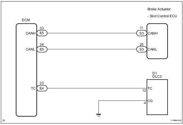
Connecting terminals TC and CG of the DLC3 causes the ECU to display the DTC by blinking the ABS warning light and/or VSC warning light.
WIRING DIAGRAM
INSPECTION PROCEDURE
NOTICE: When replacing the brake actuator assembly, perform zero point calibration (See page BC-70).
1 CHECK CAN COMMUNICATION SYSTEM
(a) Check if the CAN communication system DTC is output (See page BC-82).
Result

2 INSPECT DLC3
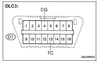
(a) Turn the ignition switch to the ON position.
(b) Measure the voltage according to the value(s) in the table below.
Standard voltage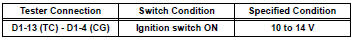
Result 

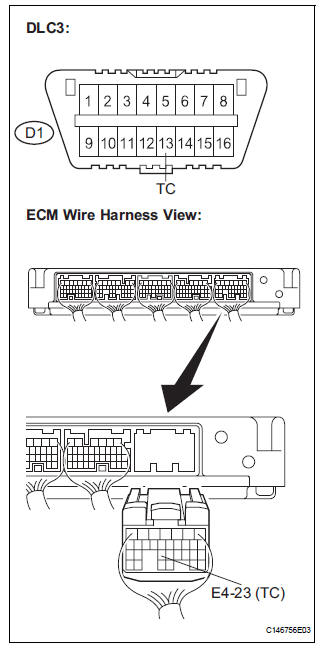
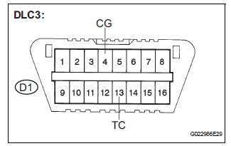
3 CHECK HARNESS AND CONNECTOR (TC of DLC3 - ECM)
(a) Turn the ignition switch off.
(b) Disconnect the ECM connector.
(c) Measure the resistance according to the value(s) in the table below.
Standard resistance 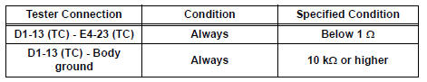

4 CHECK HARNESS AND CONNECTOR (CG of DLC3 - BODY GROUND)
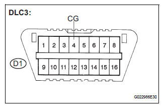
(a) Measure the resistance according to the value(s) in the table below.
Standard resistance

5 CHECK ECM (TC of DLC3 INPUT)
(a) Reconnect the ECM connector.
(b) Using SST, connect terminals TC and CG of the DLC3.
SST 09843-18040
(c) Turn the ignition switch to the ON position.
(d) Check that the check engine warning light is blinking.
Result 
HINT: If troubleshooting has been carried out according to the Problem Symptoms Table, refer back to the table and proceed to the next step before replacing the part (See page BC-79).

REPLACE BRAKE ACTUATOR ASSEMBLY
 Skid Control Buzzer Circuit
DESCRIPTION
The skid control buzzer sounds and SLIP indicator blinking during VSC
operation.
WIRING DIAGRAM
INSPECTION PROCEDURE
1 PERFORM ACTIVE TEST USING INTELLIGENT TESTER (SKID CONTROL ...
 TS and CG Terminal Circuit
DESCRIPTION
In the sensor check mode, a malfunction of the speed sensor that cannot be
detected when the vehicle is
stopped is detected while driving.
Transition to the sensor check mode can be ...
Other materials:
Programming the HomeLink® (for U.S.A. owners)
The HomeLink® compatible transceiver in your vehicle has 3 buttons
which can be programmed to operate 3 different devices. Refer to the
programming method below appropriate for the device.
Indicator light
Buttons
Programming the HomeLink®
Point the remote control for
the d ...
Vehicle Speed Signal Circuit between Stereo Component Amplifier and
Combination Meter
DESCRIPTION
This circuit is necessary for the ASL (Auto Sound Leveliser) built into the
stereo component amplifier.
Speed signals are received from the combination meter and used for the ASL.
The ASL function automatically adjusts the sound data in order to enable hearing
the clear audio ...
Short to B+ in Curtain Shield Squib LH Circuit
DTC B1168/86 Short to B+ in Curtain Shield Squib LH Circuit
DESCRIPTION
The curtain shield squib LH circuit consists of the center airbag sensor
assembly and the curtain shield
airbag assembly LH.
The circuit instructs the SRS to deploy when deployment conditions are met.
DTC B1168/86 is ...
