Toyota Sienna Service Manual: Television Display Power Source Circuit
DESCRIPTION
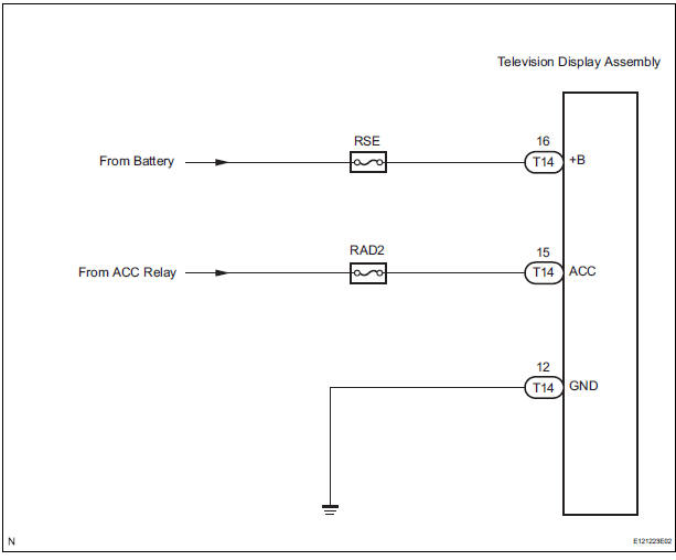
This is the power source circuit to operate the television display assembly.
WIRING DIAGRAM
INSPECTION PROCEDURE
1 INSPECT TELEVISION DISPLAY ASSEMBLY
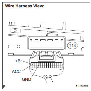
- Disconnect the connector from the television display assembly.
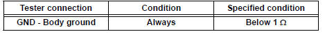
- Measure the resistance according to the value(s) in the table below.
Standard resistance
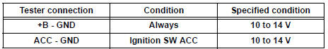
- Measure the voltage according to the value(s) in the table below.
Standard voltage
PROCEED TO NEXT CIRCUIT INSPECTION SHOWN IN PROBLEM SYMPTOMS TABLE
 Radio and Navigation Assembly Power Source Circuit
DESCRIPTION
This is the power source circuit to operate the radio and navigation
assembly.
WIRING DIAGRAM
INSPECTION PROCEDURE
1 INSPECT RADIO AND NAVIGATION ASSEMBLY
Disconnect the ...
 Navigation receiver
COMPONENTS
...
Other materials:
If the vehicle becomes
stuck
Carry out the following procedures if the tires spin or the vehicle
becomes stuck in mud, dirt, or snow:
Stop the engine. Set the parking brake and shift the shift lever to P.
Remove the mud, snow, or sand from around the stuck tire.
Place wood, stones or some other material under the tires ...
TC and CG Terminal Circuit
DESCRIPTION
Connecting terminals TC and CG of the DLC3 causes the system to enter the
self-diagnostic mode. If a
malfunction is present, DTCs will be output.
HINT:
When a particular warning light remains blinking, a ground short in the wiring
of terminal TC of the DLC3
or an internal ground ...
Reassembly
1. INSTALL FRONT DISC
(a) Aligning the matchmarks, install the front disc.
HINT:
Select the installation position where the disc has
the minimum runout.
2. INSPECT DISC RUNOUT
(a) Temporarily fasten the disc with the hub nuts.
Torque: 103 N*m (1,050 kgf*cm, 76 ft.*lbf)
(b) Using a ...
