Toyota Sienna Service Manual: Terminals of ECU
1. CHECK INSTRUMENT PANEL J/B ASSEMBLY (MULTIPLEX NETWORK BODY ECU)
- Disconnect the B6, B7 and B9 ECU connectors.
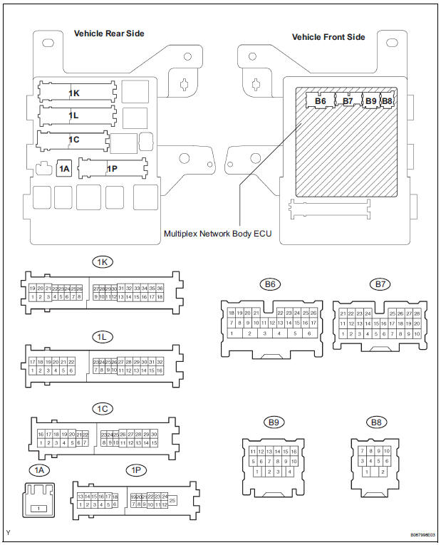
- Disconnect the 1A, 1C, 1L and 1K J/B connectors.
- Measure the voltage and resistance between each terminal of the wire harness side connectors and body ground
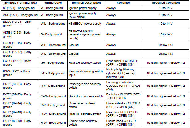
If the result is not as specified, there may be a malfunction on the wire harness side.
- Reconnect the B6, B7 and B9 ECU connectors.
- Reconnect the 1A, 1C, 1L and 1K J/B connectors.
- Measure the voltage between each terminal of the connectors and the body ground.
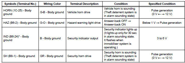
*: with Engine Immobiliser System If the result is not as specified, the J/B assembly (body ECU) may have a malfunction.
- Engine Hood Courtesy Switch Circuit
- Security Horn Circuit
- Ignition Switch Circuit
- Security Indicator Light Circuit
- ECU Power Source Circuit
 Problem symptoms table
Proceed to the reference page shown in the table below for
each malfunction symptom and troubleshoot each circuit.
HINT:
Troubleshooting of the theft deterrent system is based on the
premise tha ...
 Engine Hood Courtesy Switch Circuit
DESCRIPTION
The engine hood courtesy switch is built in the engine hood lock assembly.
The switch turns on when the
engine hood is opened and turns off when the engine hood is closed.
WIRING DIAG ...
Other materials:
Freeze frame data
1. DESCRIPTION
The ECM records vehicle and driving condition
information as freeze frame data the moment a DTC
is stored. When troubleshooting, freeze frame data
can be helpful in determining whether the vehicle
was running or stopped, whether the engine was
warmed up or not, whe ...
Customize parameters
1. Seat Belt Buzzer ON/OFF Setting
The seat belt buzzer ON/OFF setting, which is a setting
of the buzzer function of the combination meter, can
disable the driver side seat belt buzzer and front
passenger side seat belt buzzer.
NOTICE:
These buzzers should be on for safe driving.
Perform ...
Light Control Switch Circuit
DESCRIPTION
This circuit detects the state of the headlight dimmer switch.
WIRING DIAGRAM
INSPECTION PROCEDURE
1 READ VALUE OF INTELLIGENT TESTER
Connect the intelligent tester to DLC3.
Turn the ignition switch ON and push the intelligent
tester main switch ON.
Select t ...
