Toyota Sienna Service Manual: Terminals of ECU
1. CHECK TRANSPONDER KEY AMPLIFIER

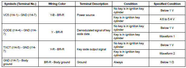
- Disconnect the I14 amplifier connector and measure the resistance between the terminal of the wire harness side connector and body ground.

If the result is not as specified, there may be a malfunction on the wire harness side.
- Reconnect the I14 amplifier connector and measure the resistance and voltage of each terminal of the connector
If the result is not as specified, the amplifier may have a malfunction.
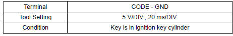
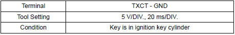
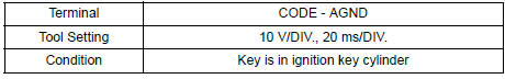
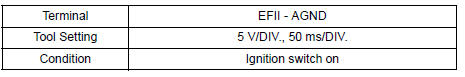
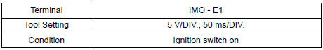
- Inspect using an oscilloscope.
- Waveform 1 (Reference):
- Waveform 2 (Reference):
2. CHECK TRANSPONDER KEY ECU ASSEMBLY
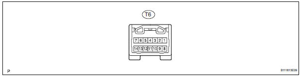
- Disconnect the T6 ECU connector and measure the resistance and voltage between each terminal of the wire harness side connector
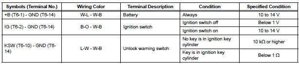
If the result is not as specified, there may be a malfunction on the wire harness side.
- Reconnect the T9 ECU connector and measure the voltage of each terminal of the connector.
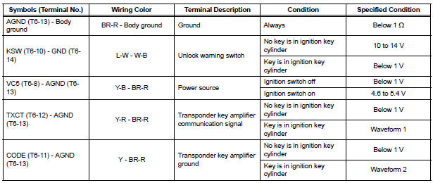
If the result is not as specified, the ECU may have a malfunction.
- Inspect using an oscilloscope.
- Wave form 1 (Reference):
- Wave form 2 (Reference):
- Wave form 3 (Reference):

- Wave form 4 (Reference):
3. CHECK ECM
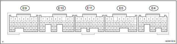
- Disconnect the E11 ECM connector and measure the resistance between the terminal of the wire harness side connector and body ground.

If the result is not as specified, there may be a malfunction on the wire harness side.
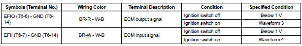
- Reconnect the E11 ECM. Measure the voltage between each terminal of the connector according to the value(s) in the table below.
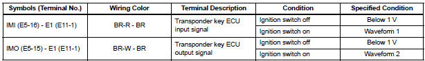
If the result is not as specified, there may be a malfunction on the wire harness side.
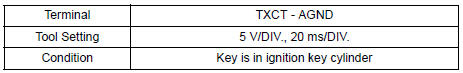
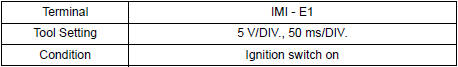
- Inspect using an oscilloscope.
- Waveform 1 (Reference):
- Waveform 2 (Reference):
 Problem symptoms table
ENGINE IMMOBILISER SYSTEM
...
 Diagnosis system
1. CHECK DLC3
The vehicle's ECU uses ISO 15765-4 for
communication protocol. The terminal arrangement
of the DLC3 complies with SAE J1962 and matches
the ISO 15765-4 format.
...
Other materials:
Data list / active test
1. DATA LIST
Using the intelligent tester to read the Data List allows
the values or states of switches, sensors, actuators and
other items to be read without removing any parts. This
non-intrusive inspection can be very useful because
intermittent conditions or signals may be discovered
befor ...
Using the rear view monitor system
Screen description
The rear view monitor system screen will be displayed if the shift
lever is shifted to R while the engine switch is in the “ON” position
(vehicles without a smart key system) or IGNITION ON mode (vehicles
with a smart key system).
Vehicle width guide line
The lin ...
Air conditioning unit
COMPONENTS
...
