Toyota Sienna Service Manual: Terminals of ECU
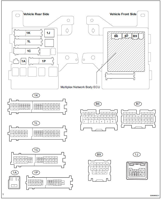
1. CHECK DRIVER SIDE J/B ASSEMBLY (MULTIPLEX NETWORK BODY ECU)
- Disconnect the 1C, 1J, 1L, 1K, 1P, B6, B7 and B9 J/ B connectors.
- Measure the voltage and resistance according to the value(s) in the table below.
Standard
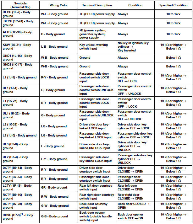
HINT:
- If the result is not as specified, there may be a malfunction on the wire harness side.
- *1: w/o Power back door
- Reconnect the J/B and ECU connectors and measure the voltage according to the value(s) in the table below.
Standard voltage
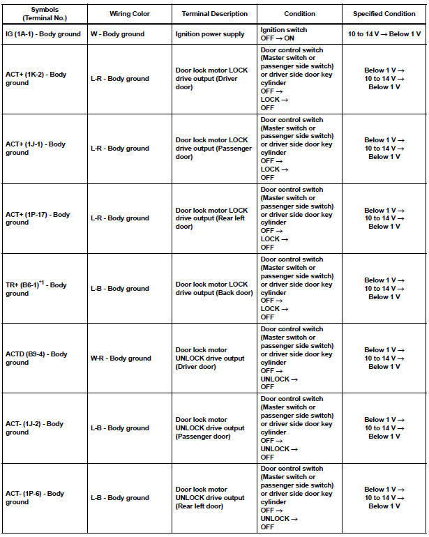
HINT:
- *1: w/o Power Back Door
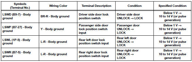
- Use an oscilloscope to check the output voltages of terminals LSWD, LSWP, LSWL and LSWR.
- If the result is not as specified, the J/B (body ECU) may have a malfunction.
2. CHECK POWER BACK DOOR ECU (w/ Power back door system)
- Disconnect the P13 and P14 ECU connectors.
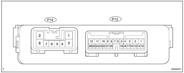
- Measure the voltage and resistance according to the value(s) in the table below.
Standard
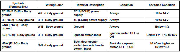
HINT: If the result is not as specified, there may be a malfunction on the wire harness side.
- Reconnect the ECU connectors and measure the voltage according to the value(s) in the table below.
Standard voltage
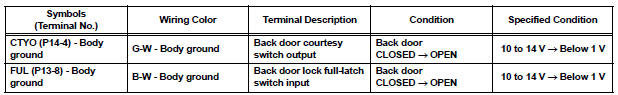
HINT: If the result is not as specified, the ECU may have a malfunction.
 Problem symptoms table
HINT:
Inspect the fuse and relay before investigating the suspected
areas shown in the table below.
POWER DOOR LOCK CONTROL SYSTEM
...
 Diagnosis system
1. CHECK DLC3
The vehicle's ECU uses ISO 15765-4 for
communication protocol. The terminal arrangement
of the DLC3 complies with SAE J1962 and matches
the ISO 15765-4 format.
...
Other materials:
How to proceed with
troubleshooting
HINT:
*: Use the intelligent tester.
1 VEHICLE BROUGHT TO WORKSHOP
2 CUSTOMER PROBLEM ANALYSIS
Confirm problem symptoms
3 CHECK MULTIPLEX COMMUNICATION SYSTEM*
Check if the multiplex communication system DTC is
output.
HINT:
The center airbag sensor assembly of this system is
co ...
Removal
1. REMOVE REAR BUMPER COVER
Put protective tape under the quarter panel.
Partially the fender liner.
HINT:
Do not remove the fender liner completely but
partially so that the bumper cover can be removed.
Remove the 2 screws and 8 clips.
Using a screwdriver, disengage the claws an ...
VC Output Circuit
DESCRIPTION
The ECM constantly uses 5 V from the battery voltages supplied to the +B (BATT)
terminal to operate the
microprocessor. The ECM also provides this power to the sensors through the VC
output circuit.
When the VC circuit is short-circuited, the microprocessor in the ECM and
sens ...
