Toyota Sienna Service Manual: Terminals of ECU
1. TELEVISION CAMERA ASSEMBLY
- Disconnect the T10 camera connector
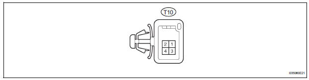
- Measure the voltage and resistance of each terminal of the wire harness side connector.
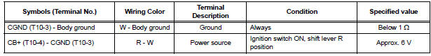
If the result is not as specified, there may be a malfunction on the wire harness side.
- Reconnect the T10 camera connector.
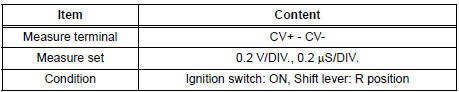
- Measure the voltage and frequency of each terminal of the connector.

If the result is not as specified, the camera may have a malfunction.
- Reference: Oscilloscope waveform
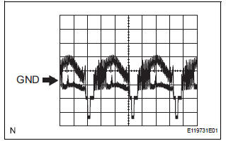
- Waveform 1
2. RADIO AND NAVIGATION ASSEMBLY
- Reverse Signal Circuit
- Display Signal Circuit between Radio and Navigation Assembly and Television Camera Assembly
 Problem symptoms table
Before inspecting the suspected areas listed in the table
below, check the fuse and relay.
Before inspecting the suspected areas listed in the table
below, check the DTCs.
Metho ...
 Reverse Signal Circuit
DESCRIPTION
The radio and navigation assembly receives a reverse signal from the
park/neutral position switch.
WIRING DIAGRAM
INSPECTION PROCEDURE
1 INSPECT RADIO AND NAVIGATION ASSEMBLY
...
Other materials:
General information
A large number of ECU controlled systems are used in the
SIENNA. In general, ECU controlled systems are considered
to be very intricate, requiring a high level of technical
knowledge to troubleshoot. However, most problem checking
procedures only involve inspecting the ECU controlled
system's c ...
Installation with LATCH system (third seat)
Manual seat
Fold the seatback while pulling
the strap. Return the seatback
and secure it at the 1st lock
position (most upright position).
Adjust the seatback to the
11th lock position.
1st lock position
11th lock position
Power seat
Fold down the seatb ...
Adjustment procedure
Manual seat
Seat position adjustment lever
Seatback angle adjustment lever
Vertical height adjustment lever (driverŌĆÖs side only)
Lumbar support adjustment switch (driverŌĆÖs side only)*
*: If equipped
Power seat
Seat position adjustment switch
Seatback angle a ...
