Toyota Sienna Service Manual: Terminals of ECU
1. JUNCTION CONNECTOR
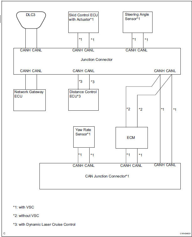
- Junction connector
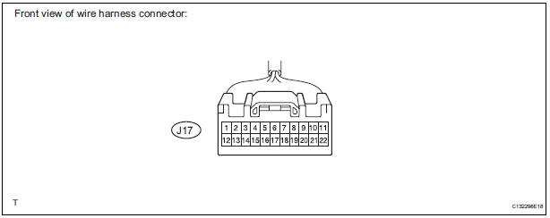
with VSC
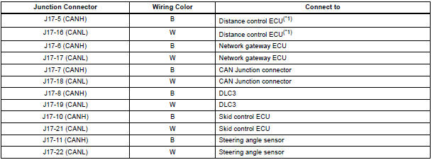
HINT: *1: with Dynamic laser cruise control
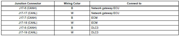
without VSC
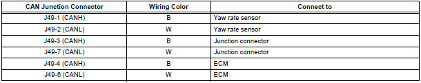
- CAN junction connector (with VSC)
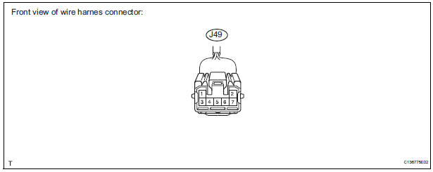
with VSC
- The connection diagram of the components which are connected to the CAN junction connector.
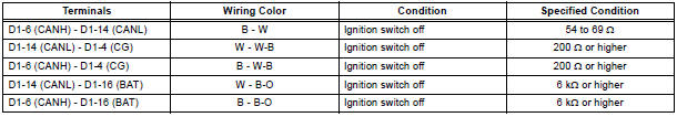
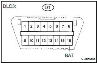
2. DLC3
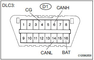
- Measure the resistance according to the value(s) in the table below.
Standard resistance
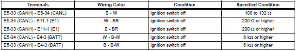
3. ECM
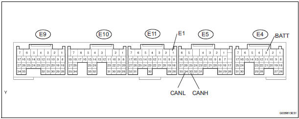
- Disconnect the connector from the ECM.
- Measure the resistance according to the value(s) in the table below
Standard resistance
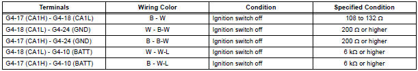
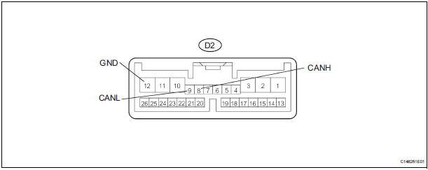
4. NETWORK GATEWAY ECU
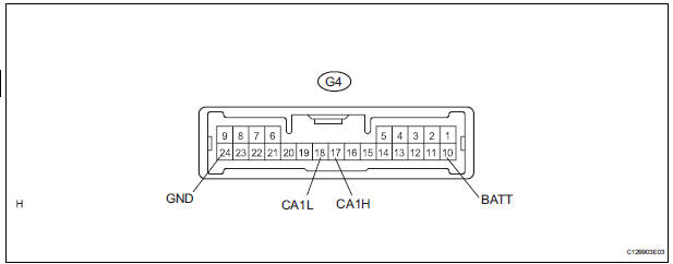
- Disconnect the connector from the netwark gateway ECU.
- Measure the resistance according to the value(s) in the table below
Standard resistance
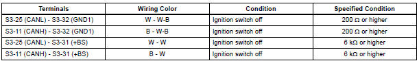
5. SKID CONTROL ECU WITH ACTUATOR
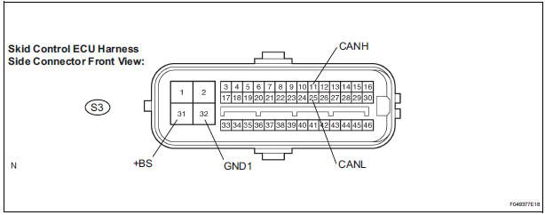
- Disconnect the connector from the skid control ECU with actuator.
- Measure the resistance according to the value(s) in the table below
Standard resistance

6. STEERING ANGLE SENSOR
- Disconnect the connector from the steering angle sensor.
- Measure the resistance according to the value(s) in the table below.
Standard resistance
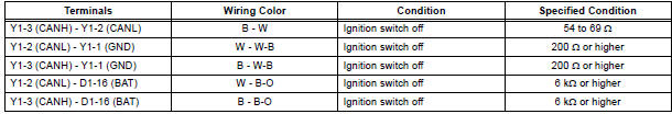
7. YAW RATE SENSOR
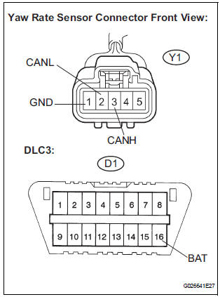
- Disconnect the connector from the yaw rate sensor.
- Measure the resistance according to the value(s) in the table below.
Standard resistance
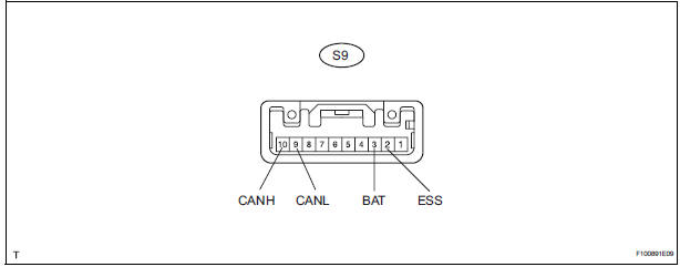
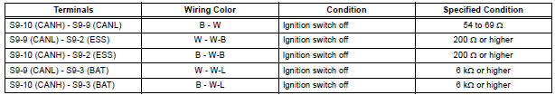
8. DISTANCE CONTROL ECU
- Disconnect the connector from the distance control ECU.
- Measure the resistance according to the value(s) in the table below.
Standard resistance
 Problem symptoms table
RESULT LIST OF CHECK CAN BUS LINE
Symptom
Suspected Area
All ECUs and sensors connected to the CAN
communication system are not displayed on intelligent
tester
CAN ...
 Diagnosis system
1. BUS CHECK
Select "BUS CHECK" from the "OBD/MOBD
MENU" screen.
HINT:
The ECUs and sensors that are properly connected
to the CAN communication system can be displaye ...
Other materials:
Reassembly
1. INSTALL REAR DIFFERENTIAL PINION SHAFT
(a) Install the 2 thrust washers to the 2 side gears.
(b) Install the 2 side gears, 2 differential pinion gears, 2
differential pinion thrust washers and differential
pinion shaft to the differential case.
HINT:
Align the holes of the differentia ...
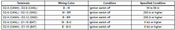
Terminals of ECU
1. CHECK DRIVER SIDE J/B ASSEMBLY (MULTIPLEX NETWORK BODY ECU)
Disconnect the 1C, 1J, 1L, 1K, 1P, B6, B7 and B9 J/
B connectors.
Measure the voltage and resistance according to
the value(s) in the table below.
Standard
HINT:
If the result is not as specified ...
Operation check
1. REMOVE CHECK FUNCTION
Check that the key reminder warning buzzer
sounds.
With the driver side door closed, insert the key
into the ignition key cylinder and then turn the
key to LOCK or ACC.
Check that the buzzer sounds intermittently if
the driver side door ...
