Toyota Sienna Service Manual: The Other Caller's Voice cannot be Heard, is too Quiet, or Distorted
INSPECTION PROCEDURE
1 CHECK CELLULAR PHONE
- Check if the voice on the other side can be heard using a cellular phone.
OK: Voice can be heard
2 CHECK NAVIGATION SYSTEM
- Check that navigation sound can be heard from the driver side speaker.
OK: Audio sound can be heard
3 CHECK SETTINGS
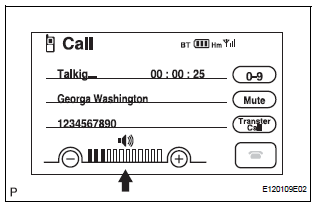
- Check if the volume level is set to low on the CALL screen.
OK: The level is not set low

4 CHECK SETTINGS

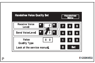
- Enter the "Handsfree Voice Quality Set" mode.
- Check if the Receive Voice Level is set to "0".
HINT: The Receive Voice Level can be set to 11 different levels, -5 to +5, with a 3 dB difference.
- Check if the Receive Voice Level is set to the minimum or maximum level.
HINT: When the Receive Voice Level is set to the minimum or maximum level, the sound may be distorted.
OK: The Receive Voice Level is set to "0".
PROCEED TO NEXT CIRCUIT INSPECTION SHOWN IN PROBLEM SYMPTOMS TABLE
 Cannot Call in a Certain Place
INSPECTION PROCEDURE
1 CHECK SURROUNDING CONDITIONS
Check if the cellular phone can make calls in a certain
place.
OK:
It can make calls
2 CHECK RECEPTION
Enter the "Informati ...
 The Other Caller cannot Hear Your Voice, or Your Voice is too Quiet or
Distorted
INSPECTION PROCEDURE
1 CHECK CELLULAR PHONE
Check if the other side can hear your voice properly.
OK:
Your voice can be heard correctly.
2 CHECK SETTINGS
Check if the mute switch is ...
Other materials:
Receiver Error
DTC C2176/76 Receiver Error
DESCRIPTION
The signals are transmitted to the tire pressure warning antenna and receiver
on the body as radio waves
and then sent to the tire pressure warning ECU.
WIRING DIAGRAM
INSPECTION PROCEDURE
NOTICE:
When replacing the tire pressure warning EC ...
Diagnostic trouble code chart
Look for output Diagnostic Trouble Codes (DTCs) (from the
DTC checks) in the appropriate section's Diagnostic Trouble
Code Chart. Use the chart to determine the trouble area and
the proper inspection procedure. A description of each of the
chart's columns is shown in the table below.
Ite ...
Correct driving posture
Adjust the angle of the seatback so that you are sitting straight up and
so that you do not have to lean forward to steer.
Adjust the seat so that you can depress the pedals fully and so that
your arms bend slightly at the elbow when gripping the steering wheel.
Lock the head rest ...
