
Toyota Sienna Service Manual: Theft deterrent system
PARTS LOCATION
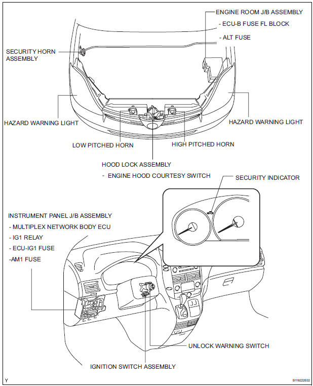
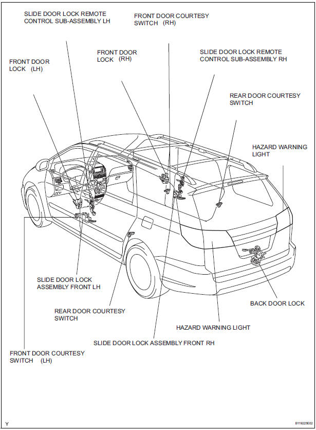
- System description
- How to proceed with troubleshooting
- Customize parameters
- Problem symptoms table
- Terminals of ECU
 Theft deterrent
...
 System description
1. OUTLINE OF THEFT DETERRENT SYSTEM
When the theft deterrent system detects that the
vehicle is being tampered with, the system sets off
the alarm, causing the horns to sound and the li ...
Other materials:
Reassembly
1. INSTALL SEAT POSITION AIRBAG SENSOR (for Driver Seat)
2. INSTALL FRONT SEAT CUSHION SHIELD LOWER LH
Install the front seat cushion shield lower LH with
the screw.
3. INSTALL FRONT SEAT CUSHION SHIELD LOWER
RH
HINT:
Use the same procedures for the RH side and LH side.
4. INSTAL ...
System diagram
1. DISC PLAYER OUTLINE
A CD player uses a laser pickup to read digital
signals recorded on CDs. By converting the digital
signals to analog, music and other content can be
played.
CAUTION:
Do not look directly at the laser pickup because
the CD player uses an invisible laser bea ...
Inspection
1. Inspect no. 3 Intake air control valve
assembly
(A) inspect actuator operation.
(1) With 26.7 Kpa (200 mm hg, 7.9 In. Hg) of
vacuum applied to the actuator, check that the
actuator rod moves.
(2) One minute after applying the vacuum, check
that the actuator rod does not return.
...
