Toyota Sienna Service Manual: Throttle Actuator Control System

DESCRIPTION
The throttle actuator is operated by the ECM, and opens and closes the throttle valve using the gears.
The opening angle of the throttle valve is detected by the Throttle Position (TP) sensor, which is mounted on the throttle body. The TP sensor provides feedback to the ECM so that it can control the throttle actuator and the throttle valve appropriately in response to driver inputs
HINT:
This ETCS (Electronic Throttle Control System) does not use a throttle cable.
MONITOR DESCRIPTION
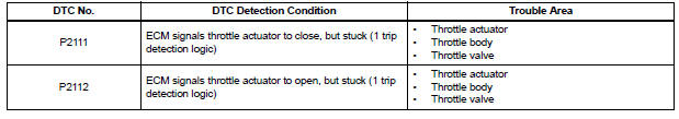
The ECM determines that there is a malfunction in the ETCS when the throttle valve remains at the fixed angle despite a high drive current from the ECM. The ECM illuminates the MIL and sets a DTC.
If the malfunction is not repaired successfully, a DTC is set when the accelerator pedal is fully depressed and released quickly (to fully open and close the throttle valve) after the engine is next started.
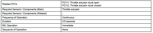
MONITOR STRATEGY
TYPICAL ENABLING CONDITIONS
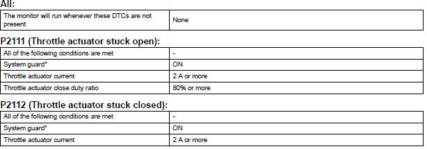
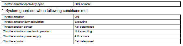
TYPICAL MALFUNCTION THRESHOLDS
FAIL-SAFE
When either of these DTCs, as well as other DTCs relating to ETCS (Electronic Throttle Control System) malfunctions, is set, the ECM enters fail-safe mode. During fail-safe mode, the ECM cuts the current to the throttle actuator off, and the throttle valve is returned to a 6° throttle angle by the return spring. The ECM then adjusts the engine output by controlling the fuel injection (intermittent fuel-cut) and ignition timing, in accordance with the accelerator pedal opening angle, to allow the vehicle to continue at a minimal speed.
If the accelerator pedal is depressed slowly, the vehicle can be driven slowly.
Fail-safe mode continues until a pass condition is detected, and the ignition switch is then turned off.
WIRING DIAGRAM
Refer to DTC P2102 (See page ES-331).
INSPECTION PROCEDURE
HINT:
Read freeze frame data using the intelligent tester. The ECM records vehicle and driving condition information as freeze frame data the moment a DTC is stored. When troubleshooting, freeze frame data can be helpful in determining whether the vehicle was running or stopped, whether the engine was warmed up or not, whether the air-fuel ratio was lean or rich, as well as other data recorded at the time of a malfunction.
1 CHECK ANY OTHER DTCS OUTPUT (IN ADDITION TO DTC P2111 OR P2112)
(a) Connect the intelligent tester to the DLC3.
(b) Turn the ignition switch to the ON position.
(c) Turn the tester on.
(d) Select the following menu items: DIAGNOSIS / ENHANCED OBD II / DTC INFO / CURRENT CODES.
(e) Read the DTCs.
Result 
HINT: If any DTCs other than P2111 or P2112 are output, troubleshoot those DTCs first.


2 INSPECT THROTTLE BODY (VISUALLY CHECK THROTTLE VALVE)
(a) Check for contamination between the throttle valve and the housing. If necessary, clean the throttle body. And check that the throttle valve moves smoothly.
OK: Throttle valve is not contaminated with foreign objects and moves smoothly.

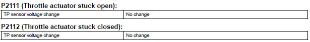
3 CHECK WHETHER DTC OUTPUT RECURS (DTC P2111 OR P2112)
(a) Connect the intelligent tester to the DLC3.
(b) Turn the ignition switch to the ON position.
(c) Turn the tester on.
(d) Clear the DTCs (See page ES-39).
(e) Start the engine, and fully depress and release the accelerator pedal quickly (to fully open and close the throttle valve).
(f) Select the following menu items: DIAGNOSIS / ENHANCED OBD II / DTC INFO / CURRENT CODES.
(g) Read the DTCs.
Result 


CHECK FOR INTERMITTENT PROBLEMS
 Throttle Actuator Control Motor Circuit
DESCRIPTION
The throttle actuator is operated by the ECM and opens and closes the
throttle valve using gears.
The opening angle of the throttle valve is detected by the Throttle Position
( ...
 Throttle Actuator Control Motor Current Range / Performance
DESCRIPTION
The ETCS (Electronic Throttle Control System) has a dedicated power supply
circuit. The voltage (+BM)
is monitored and when it is low (less than 4 V), the ECM determines that there ...
Other materials:
Disassembly
1. REMOVE COOLER THERMISTOR NO.1 (for Automatic Air Conditioning System)
(a) Disengage the 2 claw fittings and the clamp and
remove the cooler thermistor No. 1.
2. REMOVE COOLING UNIT MOTOR SUB-ASSEMBLY WITH FAN
(a) Remove the 3 screws and the cooling unit motor
sub-assembly w/ fan.
3. ...
Rear ceiling lights
Turns the lights on/off
When the personal/interior light
main switch is in the off position,
the rear ceiling lights will not turn
on even if the switch is on.
Adjusting the rear personal/interior lights angle (if equipped)
Push the edge of the light lens.
Illuminated entry system
...
Front Speed Sensor RH Circuit
DESCRIPTION
The speed sensor detects wheel speed and transmits the appropriate signals to
the ECU. These signals
are used for control of the ABS control system. The front and rear rotors have
48 serrations each.
When the rotors rotate, the magnetic field generated by the permanent magne ...
