Toyota Sienna Service Manual: Throttle / Pedal Position Sensor / Switch "D" Circuit Range / Performance
DTC P2121 Throttle / Pedal Position Sensor / Switch "D" Circuit Range / Performance
HINT: This DTC relates to the Accelerator Pedal Position (APP) sensor.
DESCRIPTION
Refer to DTC P2120

MONITOR DESCRIPTION
The accelerator pedal position sensor is mounted on the accelerator pedal bracket. The accelerator pedal position sensor has 2 sensor elements and 2 signal outputs: VPA and VPA2. VPA is used to detect the actual accelerator pedal angle (used for engine control) and VPA2 is used to detect malfunctions in VPA.
When the difference between the voltage outputs of VPA and VPA2 deviates from the standard, the ECM determines that the accelerator pedal position sensor is malfunctioning. The ECM turns on the MIL and the DTC is set.
MONITOR STRATEGY
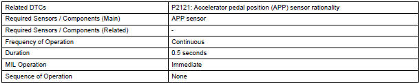
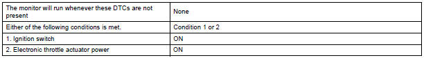
TYPICAL ENABLING CONDITIONS
TYPICAL MALFUNCTION THRESHOLDS

FAIL-SAFE
The accelerator pedal position sensor has 2 (main and sub) sensor circuits. If a malfunction occurs in either of the sensor circuits, the ECM detects the abnormal signal voltage difference between the 2 sensor circuits and switches to limp mode. In limp mode, the functioning circuit is used to calculate the accelerator pedal opening angle to allow the vehicle to continue driving. If both circuits malfunction, the ECM regards the opening angle of the accelerator pedal as being fully closed. In this case, the throttle valve remains closed as if the engine is idling.
If a pass condition is detected and then the ignition switch is turned off, the fail-safe operation stops and the system returns to a normal condition.
WIRING DIAGRAM
Refer to DTC P2120.
INSPECTION PROCEDURE
HINT: Read freeze frame data using the intelligent tester. The ECM records vehicle and driving condition information as freeze frame data the moment a DTC is stored. When troubleshooting, freeze frame data can be helpful in determining whether the vehicle was running or stopped, whether the engine was warmed up or not, whether the air-fuel ratio was lean or rich, as well as other data recorded at the time of a malfunction.
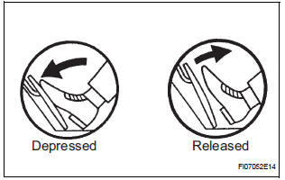
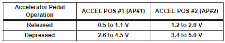
1 READ VALUE OF INTELLIGENT TESTER (ACCEL POS #1 AND ACCEL POS #2)
- Connect the intelligent tester to the DLC3.
- Turn the ignition switch to the ON position and turn the tester on.
- Select the following menu items: DIAGNOSIS / ENHANCED OBD II / DATA LIST / ALL / ACCEL POS #1 and ACCEL POS #2.
- Read the values displayed on the tester.
Standard voltage
2 CHECK HARNESS AND CONNECTOR (ACCELERATOR PEDAL POSITION SENSOR - ECM)
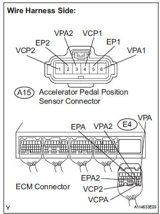
- Disconnect the A15 Accelerator Pedal Position (APP) sensor connector.
- Disconnect the E4 ECM connector.
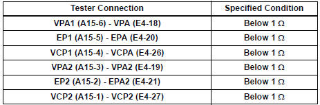
- Measure the resistance according to the value(s) in the table below.
Standard resistance : Check for open
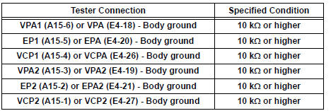
Check for short
- Reconnect the APP sensor connector.
- Reconnect the ECM connector
3 REPLACE ACCELERATOR PEDAL ROD
- Replace the accelerator pedal rod assembly
4 CHECK WHETHER DTC OUTPUT RECURS (ACCELERATOR PEDAL POSITION SENSOR DTCS)
- Connect the intelligent tester to the DLC3.
- Turn the ignition switch to the ON position and turn the tester on.
- Clear the DTCs.
- Start the engine.
- Allow the engine to idle for 15 seconds.
- Select the following menu items on the tester: DIAGNOSIS / ENHANCED OBD II / DTC INFO / CURRENT CODES.
- Read the DTCs.
Result

REPLACE ECM
 Throttle / Pedal Position Sensor/ Switch
DTC P2120 Throttle / Pedal Position Sensor / Switch "D"
Circuit
DTC P2122 Throttle / Pedal Position Sensor / Switch "D"
Circuit Low Input
DTC P2123 Throttle / Pedal Position Se ...
 Oxygen (A/F) Sensor Signal Stuck
DTC P2195 Oxygen (A/F) Sensor Signal Stuck Lean (Bank 1
Sensor 1)
DTC P2196 Oxygen (A/F) Sensor Signal Stuck Rich (Bank 1
Sensor 1)
DTC P2197 Oxygen (A/F) Sensor Signal Stuck Lean (Bank 2
Sensor ...
Other materials:
Dtc check / clear
Notice:All the stored dtcs and freeze frame data are
erased if:
1) the ecm is changed from normal mode to check mode
or vice versa; or 2) the ignition switch is turned from on
to acc or off while in check mode.
Before changing modes, always check and make a note
of any dt ...
Installation
HINT:
Use the same procedures for the RH side and LH side.
The procedures listed below are for the LH side.
1. INSTALL FRONT AIRBAG SENSOR LH
Check that the ignition switch is off.
Check that the battery negative (-) terminal is
disconnected.
CAUTION: ...
Installation
1. INSTALL CENTER AIRBAG SENSOR ASSEMBLY
Check that the ignition switch is off.
Check that the battery negative (-) terminal is
disconnected.
CAUTION:
After disconnecting the negative battery
terminal, wait for at least 90 seconds before
starting the operation.
Temporar ...
