Toyota Sienna Service Manual: Tire Pressure Warning Light Circuit
DESCRIPTION
If the ECU detects trouble, the tire pressure warning light blinks (comes on after blinking for 1 minute) and tire pressure monitor is cancelled at the same time. At this time, the ECU records a DTC in the memory.
Connect terminals TC and CG of DLC3 to make the tire pressure warning light blink and output the DTC.
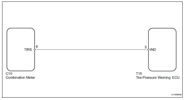
WIRING DIAGRAM
INSPECTION PROCEDURE
NOTICE: When replacing the tire pressure warning ECU, read the transmitter IDs stored in the old ECU using the intelligent tester and write them down before removal.
It is necessary to perform initialization (See page TW-23) after registration (See page TW-20) of the transmitter IDs into the tire pressure warning ECU, after the ECU has been replaced.
HINT: This procedure must be performed according to the PROBLEM SYMPTOMS TABLE.
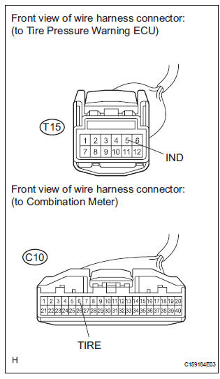
1 CHECK HARNESS AND CONNECTOR (COMBINATION METER - TIRE PRESSURE WARNING ECU)
(a) Disconnect the C10 combination meter connector.
(b) Disconnect the T15 tire pressure warning ECU connector.
(c) Measure the resistance according to the value(s) in the table below.
Standard resistance 

2 INSPECT COMBINATION METER
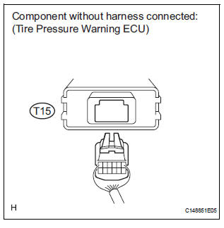
(a) Disconnect the connector from the tire pressure warning ECU.
(b) Turn the ignition switch to the ON position, and check if the tire pressure warning light illuminates.
Result 


REPLACE TIRE PRESSURE WARNING ECU (See page TW-87)
 Tire Pressure Warning Reset Switch Circuit
DESCRIPTION
The ECU enters the initialization mode and performs initialization
automatically, when the tire pressure
warning ECU receives the signal from the tire pressure warning reset switch. If ...
 ECU Power Source Circuit
DESCRIPTION
This is the power source for the tire pressure warning ECU.
WIRING DIAGRAM
INSPECTION PROCEDURE
NOTICE:
When replacing the tire pressure warning ECU, read the transmitter IDs
st ...
Other materials:
Installation
1. INSTALL BRAKE ACTUATOR
NOTICE:
Do not remove the hole plugs before connecting the
brake tubes. New actuators are filled with brake
fluid.
(a) Install the brake actuator assembly with the 2 nuts.
Torque: 5.4 N*m (55 kgf*cm, 48 in.*lbf)
2. INSTALL BRAKE ACTUATOR WITH BRACKET
(a) Insta ...
Reassembly
1. INSTALL LIGHT CONTROL ECU (DISCHARGE HEADLIGHT)
Install a new headlight leveling motor base packing.
Install the headlight leveling motor assembly as
shown in the illustration.
Connect the connector with the claw
Install the light control ECU with the 2 ...
Calculation formula for your vehicle
Cargo capacity
Total load capacity (vehicle capacity weight)
When 2 people with the combined weight of A lb. (kg) are riding in
your vehicle, which has a total load capacity (vehicle capacity weight)
of B lb. (kg), the available amount of cargo and luggage load capacity
will be C lb. ...
