Toyota Sienna Service Manual: Tire pressure warning reset switch
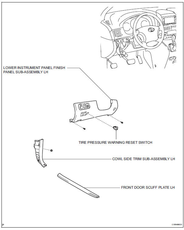
COMPONENTS
 Installation
1. INSTALL TIRE PRESSURE WARNING ECU
(a) Connect the connector to the tire pressure warning
ECU.
(b) Install the tire pressure warning ECU with the screw.
2. INSTALL INSTRUMENT PANEL SAFET ...
 Removal
1. DISCONNECT CABLE FROM NEGATIVE BATTERY
TERMINAL
2. REMOVE FRONT DOOR SCUFF PLATE LH
3. REMOVE COWL SIDE TRIM SUB-ASSEMBLY LH
4. REMOVE LOWER INSTRUMENT PANEL FINISH
PANEL SUB-ASSEMBLY LH (See ...
Other materials:
Using the steering
wheel switches
The steering wheel switches can be used to operate a connected
cellular phone.
Operating a telephone using the steering wheel switches
Volume switch
Increase/Decrease the volume
Press and hold:
Continuously increase/
decrease the volume
Cursor switch
Select a list/t ...
Seating configuration variation
Cargo capacity
Weight of the removed second
seat
If removing the second seats, it is possible to load extra cargo equal
to the weight of the removed seats.
(Cargo capacity) = (Total load capacity) - (Total weight of occupants) +
(Weight of the removed second seats)
Second seats w ...
Front axle hub bolt
COMPONENTS
Replacement
HINT:
Replace the RH side using the same procedures as for the
LH side.
1. REMOVE FRONT WHEEL
2. SEPARATE FRONT DISC BRAKE CALIPER
ASSEMBLY LH (See page AH-5)
3. REMOVE FRONT DISC
4. REMOVE FRONT AXLE LH HUB BOLT
(a) Temporarily install the 2 nuts and washers ...
