
Toyota Sienna Service Manual: Tire pressure warning valve and transmitter
Components
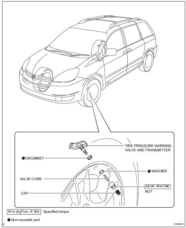
 Installation
1. INSTALL TIRE PRESSURE WARNING RECEIVER ASSEMBLY
(a) Connect the connector.
(b) Install the tire pressure warning receiver assembly
with the bolt.
Torque: 5.0 N*m (51 kgf*cm, 44 in.*lbf) ...
 Removal
1. REMOVE FRONT WHEEL
2. REMOVE REAR WHEEL
3. REMOVE TIRE PRESSURE WARNING VALVE AND TRANSMITTER
(a) Remove the valve core and cap, and release the air
from the tire.
(b) After ensuring tha ...
Other materials:
Bluetooth® Audio
Listening to Bluetooth® Audio
The Bluetooth® audio system enables the user to enjoy music
played on a portable player from the vehicle speakers via wireless
communication.
When a Bluetooth® device cannot be connected, check the connection
status on the “Bluetooth* Audio� screen. If the ...
Installation
1. INSTALL KNOCK CONTROL SENSOR
Install the 2 knock control sensors with the 2 bolts
as shown in the illustration.
Torque: 20 N*m (204 kgf*cm, 15 ft.*lbf)
Connect the 2 knock control sensor connectors.
2. INSTALL INTAKE MANIFOLD
3. INSTALL FUEL MAIN TUBE SUB-ASSEMBLY
4 ...
Wiper Signal Circuit
DESCRIPTION
The distance control ECU detects wiper operation. If the windshield wipers
operate in the HI or LO mode,
the cruise control is canceled and the warning sound "pong" is emitted once. In
addition, the following
warnings will continue until the cruise control main switch is ...
