Toyota Sienna Service Manual: Torque Converter Clutch Solenoid Circuit

DESCRIPTION
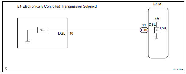
The shift solenoid valve DSL is turned "ON" and "OFF" by signals from the ECM
in order to control the
hydraulic pressure operation, the lock-up relay valve, which then controls
operation of the lock-up clutch.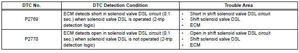
MONITOR DESCRIPTION
Torque converter lock-up is controlled by the ECM based on engine rpm, engine load, engine temperature, vehicle speed, transmission temperature, and shift range selection. The ECM determines the lock-up status of the torque converter by comparing the engine rpm (NE) to the input turbine rpm (NT).
The ECM calculates the actual transmission gear by comparing input turbine rpm (NT) to counter gear rpm (NC). When conditions are appropriate, the ECM requests "lock-up" by applying control voltage to the shift solenoid DSL. When the DSL is opened, it applies pressure to the lock-up relay valve and locks the torque converter clutch. If the ECM detects an open or short in the DSL solenoid circuit, the ECM interprets this as a fault in the DSL solenoid or circuit. The ECM will turn on the MIL and store the DTC.
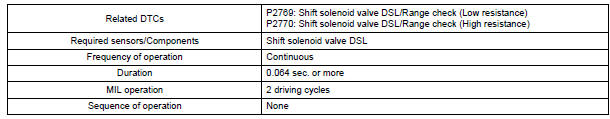
MONITOR STRATEGY
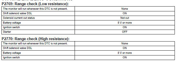
TYPICAL ENABLING CONDITIONS

TYPICAL MALFUNCTION THRESHOLDS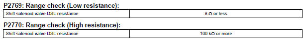
COMPONENT OPERATING RANGE
WIRING DIAGRAM
INSPECTION PROCEDURE
1 INSPECT TRANSMISSION WIRE (DSL)
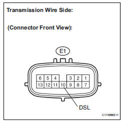
(a) Disconnect the transmission wire connector from the transaxle.
(b) Measure the resistance according to the value(s) in the table below.
Standard resistance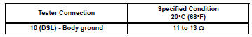


2 CHECK HARNESS AND CONNECTOR (TRANSMISSION WIRE - ECM)
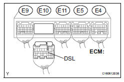
(a) Connect the transmission wire connector.
(b) Disconnect the ECM connector.
(c) Measure the resistance according to the value(s) in the table below.
Standard resistance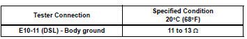


REPLACE ECM
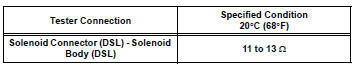
3 INSPECT SHIFT SOLENOID VALVE DSL

(a) Remove the shift solenoid valve DSL.
(b) Measure the resistance according to the value(s) in the table below.
Standard resistance
(c) Connect the positive (+) lead to the terminal of the solenoid connector, and the negative (-) lead to the solenoid body.
OK: The solenoid valve makes an operating sound.

REPAIR OR REPLACE TRANSMISSION WIRE
 Pressure Control Solenoid "D" Electrical (Shift
Solenoid Valve SLT)
Pressure Control Solenoid "D" Electrical (Shift
Solenoid Valve SLT)
DESCRIPTION
The linear solenoid valve (SLT) controls the transmission line pressure for
smooth transmission operation
based on signals from the throttle position sensor and the vehicle speed senso ...
Other materials:
Sliding doors
Vehicles without power sliding doors
The sliding doors can be opened and closed using the sliding
door handle. The sliding door can be locked and unlocked using
the wireless remote control, door lock switch or inside lock
knob.
Vehicles with power sliding doors
...
High Temperature
DTC 63-47 High Temperature
DESCRIPTION
DTC No.
DTC Detection Condition
Trouble Area
63-47
Sensor detects that CD unit temperature is high (Over
80C).
Radio and navigation assembly
INSPECTION PROCEDURE
HINT:
After the inspection is completed, c ...
Solar Sensor Circuit (Driver Side)
DESCRIPTION
The solar sensor, which is installed on the upper side of the instrument
panel, detects sunlight and
controls the air conditioning in AUTO mode. The output voltage from the solar
sensor varies according to
the amount of sunlight. When the sunlight increases, the output voltage ...
