Toyota Sienna Service Manual: Trouble in Passenger Airbag ON / OFF Indicator
DESCRIPTION
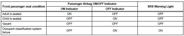
The occupant classification system detects the front passenger seat condition. It then informs a passenger of the front passenger airbag, the front seat side airbag RH and front seat belt pretensioner RH condition (activated/not activated) by the passenger airbag ON/OFF indicator.
HINT: Approximately 6 seconds after the ignition switch is turned to the ON position, the passenger airbag ON/ OFF indicator will be ON/OFF depending on the conditions listed below.
INSPECTION PROCEDURE
1 CHECK SRS WARNING LIGHT
- Turn the ignition switch to the ON position, and check the SRS warning light condition.
HINT: If this trouble occurs, the SRS warning light is off. If it is on, a DTC is output. Troubleshoot for the output DTC.
OK: After the primary check period, SRS warning light goes off. HINT: The primary check period is approximately 6 seconds after the ignition switch is turned to the ON position
2 PERFORM ZERO POINT CALIBRATION
- Turn the ignition switch to the LOCK position.
- Connect the intelligent tester to the DLC3.
- Turn the ignition switch to the ON position.
- Using the intelligent tester, perform "Zero point calibration" (28).
OK: "COMPLETE" is displayed
3 PERFORM SENSITIVITY CHECK
- Using the intelligent tester, perform "Sensitivity check" (28).
Standard value: 27 to 33 kg (59.52 to 72.75 lb)
END
4 RETIGHTEN FRONT SEAT ASSEMBLY RH BOLT
- Turn the ignition switch to the LOCK position.
- Loosen the 4 installation bolts of the front seat assembly RH.
- Tighten the 4 installation bolts of the front seat assembly RH to the specified torque.
Torque: 37 N*m (375 kgf*cm, 27 ft.*lbf)
5 PERFORM ZERO POINT CALIBRATION
- Connect the intelligent tester to the DLC3.
- Turn the ignition switch to the ON position.
- Using the intelligent tester, perform "Zero point calibration" (28).
OK: "COMPLETE" is displayed.
6 PERFORM SENSITIVITY CHECK
- Using the intelligent tester, perform "Sensitivity check" (28).
Standard value: 27 to 33 kg (59.52 to 72.75 lb)
END
7 CHECK CONNECTORS
- Turn the ignition switch to the LOCK position.
- Disconnect the negative (-) terminal cable from the battery, and wait for at least 90 seconds.
- Check the connectors are properly connected to the
occupant classification ECU and the 4 occupant
classification sensors.
OK: The connectors are connected.
- Disconnect the connectors from the occupant classification ECU and the 4 occupant classification sensors.
- Check the connectors are not damaged or deformed.
OK: The connectors are properly normal.
8 CHECK DTC
- Connect the connectors to the occupant classification ECU and the 4 occupant classification sensors.
- Connect the negative (-) terminal cable to the battery.
- Turn the ignition switch to the ON position, and wait for at least 60 seconds.
- Turn the ignition switch to the LOCK position.
- Clear the DTCs stored in the memory.
- Turn the ignition switch to the ON position, and wait for at least 60 seconds.
- Check the DTCs (35).
OK: DTC is not output.
9 REPLACE OCCUPANT CLASSIFICATION ECU
- Turn the ignition switch to the LOCK position.
- Disconnect the negative (-) terminal cable from the battery, and wait for at least 90 seconds.
- Replace the occupant classification ECU
10 PERFORM ZERO POINT CALIBRATION
- Connect the negative (-) terminal cable to the battery.
- Connect the intelligent tester to the DLC3.
- Turn the ignition switch to the ON position.
- Using the intelligent tester, perform "Zero point calibration" (28).
OK: "COMPLETE" is displayed.
11 PERFORM SENSITIVITY CHECK
- Using the intelligent tester, perform "Sensitivity check" (28).
Standard value: 27 to 33 kg (59.52 to 72.75 lb)
END
 Sleep Operation Failure of Occupant Classification
ECU
Sleep Operation Failure of Occupant Classification
ECU
DTC B1796 Sleep Operation Failure of Occupant Classification
ECU
DESCRIPTION
During sleep mode, the occupant classification ECU reads the condition of
each sensor while the ignition
switch is of ...
 Steering pad
Components
...
Other materials:
MIL Circuit
DESCRIPTION
The MIL (Malfunction Indicator Lamp) is used to indicate vehicle malfunctions
detected by the ECM.
When the ignition switch is turned to the ON position, power is supplied to the
MIL circuit, and the ECM
provides the circuit ground which illuminates the MIL.
The MIL operation ...
Data list / active test
HINT:
By accessing the DATA LIST displayed on the intelligent
tester, you can perform such functions as reading the values
of switches and sensors without removing any parts. Reading
the DATA LIST as the first step in troubleshooting is one
method to shorten labor time.
1. DATA LIST FOR CENTER ...
Inspection
1. INSPECT SPEED SENSOR (NT SENSOR)
(a) Disconnect the speed sensor connector from the
transaxle.
(b) Measure the resistance according to the value(s) in
the table below.
AISIN made:
TOYOTA made:
2. INSPECT SPEED SENSOR (NC SENSOR)
(a) Disconnect the speed sensor connector from ...
