Toyota Sienna 2010-2026 Owners Manual: Using the rear view monitor system
Screen description
The rear view monitor system screen will be displayed if the shift lever is shifted to R while the engine switch is in the “ON” position (vehicles without a smart key system) or IGNITION ON mode (vehicles with a smart key system).
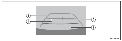
- Vehicle width guide line
The line indicates a guide path when the vehicle is being backed straight
up.
The displayed width is wider than the actual vehicle width.
- Vehicle center guide line These lines indicate the estimated vehicle center on the ground.
- Distance guide line
The line shows distance behind the vehicle, a point approximately 1.5 ft.
(0.5 m) (red) from the edge of the bumper.
- Distance guide line
The line shows distance behind the vehicle, a point approximately 3 ft.
(1 m) (blue) from the edge of the bumper.
 Rear view monitor
system
Rear view monitor
system
The rear view monitor system assists the driver by displaying an
image of the view behind the vehicle and guide lines while backing
up, for example while parking.
The screen illustrations used in t ...
 Rear view monitor system precautions
Area displayed on screen
The rear view monitor system
displays an image of the view
from the bumper of the rear
area of the vehicle.
The image on the rear view monitor system can be adjusted.
...
Other materials:
System description
1. BRIEF DESCRIPTION
The CAN (Controller Area Network) is a serial data
communication system for real time application. It is
a vehicle multiplex communication system which
has a high communication speed (500 kbps) and
the ability to detect malfunctions.
By pairing the CANH and CANL bu ...
Inspection
1. V
(a) Inspect VSV operation.
(1) Using an ohmmeter, measure the resistance
according to the value(s) in the table below.V
Standard resistance
If the result is not as specified, replace the
vsv.
(B) inspect the vsv for ground.
(1) Using an ohmmeter, measure the resistance
accordin ...
Pressure Control Solenoid "D" Performance (Shift
Solenoid Valve SLT)
SYSTEM DESCRIPTION
The linear solenoid valve (SLT) controls the transmission line pressure for
smooth transmission operation
based on signals from the throttle position sensor and the vehicle speed sensor.
The ECM adjusts the
duty ratio (*) of the SLT solenoid valve to control hydraulic line ...
