Toyota Sienna Service Manual: Vacuum switching valve
Components
REMOVAL
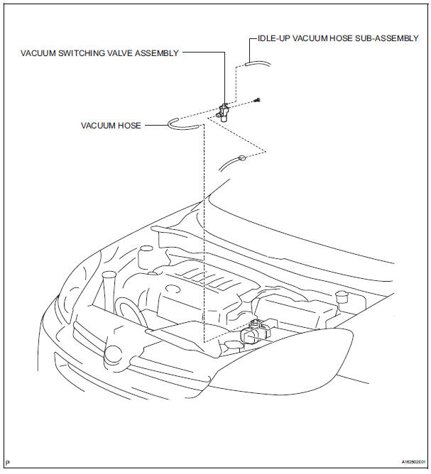
1. REMOVE VACUUM SWITCHING VALVE ASSEMBLY
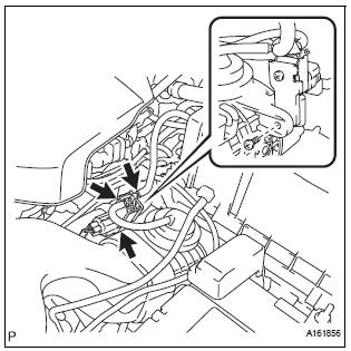
(a) Remove the 2 vacuum hoses and vacuum switching valve connector.
(b) Remove the screw and vacuum switching valve.
 Vacuum tank
On-vehicle inspection
1. Inspect air cleaner cap sub-assembly
(A) check that air flows from port b to port a.
(B) apply 60 kpa (450 mm hg, 18 in. Hg) of vacuum to
port b. Check that there is ...
 Inspection
1. V
(a) Inspect VSV operation.
(1) Using an ohmmeter, measure the resistance
according to the value(s) in the table below.V
Standard resistance
If the result is not as specified, replace t ...
Other materials:
Removal
1. Disconnect battery negative terminal
2. Remove instrument cluster finish panel
sub-assembly center
Hint:
(see page ip-9)
3. Remove transmission control cable assembly
(a) Remove the nut from the control shaft lever.
(b) Disconnect the transmission control cable assembly
from the con ...
Engine Coolant Temperature Receiver Gauge Malfunction
DESCRIPTION
The meter CPU receives engine coolant temperature signals from the ECM via
the multiplex
communication lines. The meter CPU displays engine coolant temperature that is
calculated based on the
data received from the ECM.
WIRING DIAGRAM
INSPECTION PROCEDURE
HINT:
If there is ...
Gauges and meters
The displayed content may differ depending on the type of meter.
Vehicles with monochrome display
Vehicles with color display
Tachometer
Displays the engine speed in revolutions per minute
Multi-information display
Presents the driver with a variety of driving-related d ...
