Toyota Sienna Service Manual: VC Output Circuit
DESCRIPTION
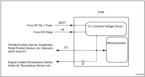
The ECM constantly uses 5 V from the battery voltages supplied to the +B (BATT) terminal to operate the microprocessor. The ECM also provides this power to the sensors through the VC output circuit.
When the VC circuit is short-circuited, the microprocessor in the ECM and sensors that are supplied power through the VC circuit are inactivated because the power is not supplied from the VC circuit. Under this condition, the system does not start up and the MIL does not illuminate even if the system malfunctions.
HINT: Under normal conditions, the MIL is illuminated for several seconds when the ignition switch is first turned to the ON position. The MIL goes off when the engine is started.
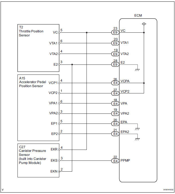
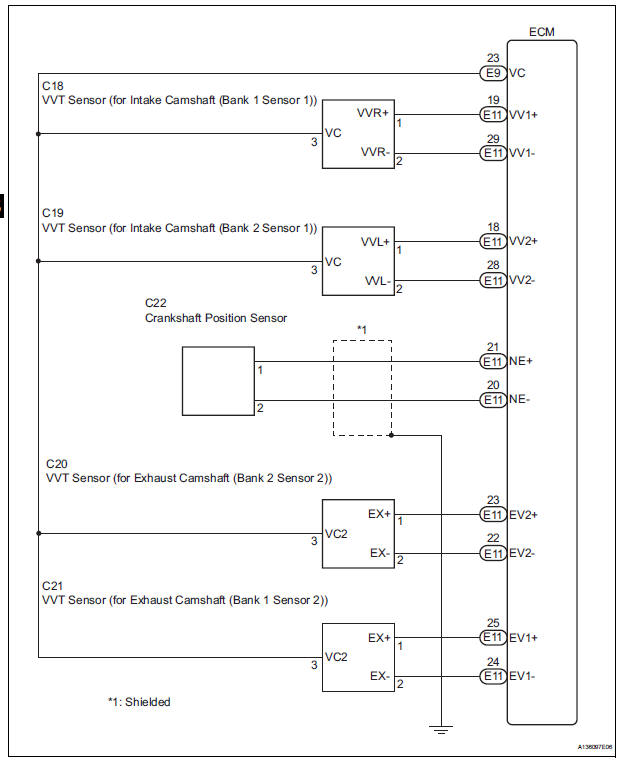
WIRING DIAGRAM
INSPECTION PROCEDURE
1 CHECK MIL
- Check that the Malfunction Indicator Lamp (MIL) lights up when turning the ignition switch to the ON position.
OK: MIL lights up.
2 CHECK CONNECTION BETWEEN INTELLIGENT TESTER AND ECM
- Connect the intelligent tester to the DLC3.
- Turn the ignition switch to the ON position and turn the tester on.
- Check the communication between the tester and ECM.
Result

3 CHECK THROTTLE BODY (CHECK MIL ILLUMINATED)
- Disconnect the throttle body connector.
- Turn the ignition switch to the ON position.
- Check the MIL.
Result

- Reconnect the throttle body connector.
4 CHECK ACCELERATOR PEDAL ROD (CHECK MIL ILLUMINATED)
- Disconnect the accelerator pedal position sensor connector.
- Turn the ignition switch to the ON position.
- Check the MIL
Result

- Reconnect the accelerator pedal position sensor connector.
5 CHECK VVT SENSOR FOR INTAKE CAMSHAFT BANK 1 (CHECK MIL ILLUMINATED)
- Disconnect the VVT sensor for intake camshaft bank 1 connector.
- Turn the ignition switch to the ON position.
- Check the MIL.
Result

- Reconnect the VVT sensor for intake camshaft bank 1 connector.
6 CHECK VVT SENSOR FOR EXHAUST CAMSHAFT BANK 1 (CHECK MIL ILLUMINATED)
- Disconnect the VVT sensor for exhaust camshaft bank 1 connector.
- Turn the ignition switch to the ON position.
- Check the MIL.
Result

- Reconnect the VVT sensor for exhaust camshaft bank 1 connector
7 CHECK VVT SENSOR FOR INTAKE CAMSHAFT BANK 2 (CHECK MIL ILLUMINATED)
- Disconnect the VVT sensor for intake camshaft bank 2 connector.
- Turn the ignition switch to the ON position.
- Check the MIL.
Result

- Reconnect the VVT sensor for intake camshaft bank 2 connector.
8 CHECK VVT SENSOR FOR EXHAUST CAMSHAFT BANK 2 (CHECK MIL ILLUMINATED)
- Disconnect the VVT sensor for exhaust camshaft bank 2 connector.
- Turn the ignition switch to the ON position.
- Check the MIL.
Result

- Reconnect the VVT sensor for exhaust camshaft bank 2 connector.
9 CHECK CHARCOAL CANISTER ASSEMBLY (CHECK MIL ILLUMINATED)
- Disconnect the canister pump module connector.
- Turn the ignition switch to the ON position.
- Check the MIL.
Result

- Reconnect the canister pump module connector.
10 CHECK HARNESS AND CONNECTOR
- Disconnect the throttle body connector.
- Disconnect the accelerator pedal position sensor connector.
- Disconnect the VVT sensor for intake camshaft bank 1 connector.
- Disconnect the VVT sensor for exhaust camshaft bank 1 connector.
- Disconnect the VVT sensor for intake camshaft bank 2 connector.
- Disconnect the VVT sensor for exhaust camshaft bank 2 connector.
- Disconnect the canister pump module connector.
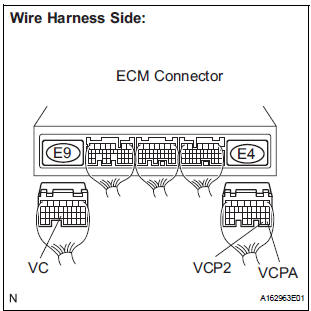
- Disconnect the E9 and E4 ECM connectors.
- Measure the resistance according to the value(s) in the table below.
Standard resistance (Check for short)

- Reconnect the ECM connectors.
- Reconnect the canister pump module connector.
- Reconnect the VVT sensor for exhaust camshaft bank 2 connector.
- Reconnect the VVT sensor for intake camshaft bank 2 connector.
- Reconnect the VVT sensor for exhaust camshaft bank 1 connector.
- Reconnect the VVT sensor for intake camshaft bank 1 connector.
- Reconnect the accelerator pedal position sensor connector.
- Reconnect the throttle body connector.
REPLACE ECM
 ECM Power Source Circuit
DESCRIPTION
When the ignition switch is turned to the ON position, the battery voltage is
applied to terminal IGSW of
the ECM. The ECM MREL output signal causes a current to flow to the coil,
cl ...
 Fuel Pump Control Circuit
DESCRIPTION
The FUEL PUMP relay switches the fuel pump speed according to the engine
conditions. The fuel pump
operates when the ECM receives the starter-operating signal (STA) and
crankshaft-ro ...
Other materials:
Camshaft Position "A" Actuator Circuit
DESCRIPTION
The Variable Valve Timing (VVT) system includes the ECM, Oil Control Valve
(OCV) and VVT controller.
The ECM sends a target duty-cycle control signal to the OCV. This control signal
regulates the oil
pressure supplied to the VVT controller. Camshaft timing control is perform ...
Wiper and washer system
PRECAUTION
1. PRECAUTION OF WASHER NOZZLE ADJUSTMENT
Do not clean or adjust the washer nozzle with a
safety pin, etc. because;
the washer nozzle tip is made of resin and could
be damaged.
adjustment is not necessary because the
washer nozzle is a spray type.
...
Removal
1. PRECAUTION
CAUTION: Be sure to read "PRECAUTION" thoroughly before
servicing.
2. DISCONNECT CABLE FROM NEGATIVE BATTERY
TERMINAL
CAUTION:
Wait for 90 seconds after disconnecting the cable to
prevent the airbag working.
3. PLACE FRONT WHEELS FACING STRAIGHT AHEAD
4. REMOVE STEE ...
