Toyota Sienna Service Manual: Vehicle Speed Signal Circuit between Radio and Navigation Assembly and Combination Meter
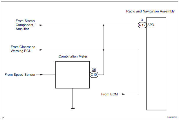
DESCRIPTION The radio and navigation assembly receives a vehicle speed signal from the combination meter and information about the GPS antenna, and then adjusts vehicle position.
HINT:
- A voltage of 12 V or 5 V is output from each ECU and then input to the combination meter. The signal is changed to a pulse signal at the transistor in the combination meter. Each ECU controls the respective system based on the pulse signal.
- If a short occurs in an ECU, all systems in the diagram below will not operate normally.
WIRING DIAGRAM
INSPECTION PROCEDURE
1 CHECK OPERATION OF SPEEDOMETER
- Drive the vehicle and check if the function of the speedometer on the combination meter is normal.
OK: Actual vehicle speed and the speed indicated on the speedometer are the same
HINT: The vehicle speed sensor is functioning normally when the indication on the speedometer is normal.
2 INSPECT RADIO AND NAVIGATION ASSEMBLY
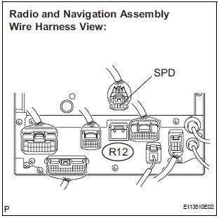
- Disconnect the radio and navigation assembly connector R12.
- Measure the voltage.
- Jack up either one of the drive wheels.
- Move the shift lever to the neutral position.
- Turn the ignition switch to the ON position
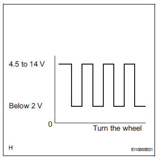
- Measure the voltage between terminal SPD of the radio and navigation assembly and body ground when the drive wheels are turned slowly.
OK: Voltage pulses as shown in the illustration.
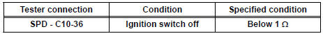
3 CHECK HARNESS AND CONNECTOR (COMBINATION METER - RADIO AND NAVIGATION ASSEMBLY)
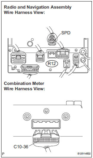
- Disconnect the radio and navigation assembly connector R12 and combination meter connector C10.
- Measure the resistance according to the value(s) in the table below.
Standard resistance
4 CHECK HARNESS AND CONNECTOR (COMBINATION METER - RADIO AND NAVIGATION ASSEMBLY)
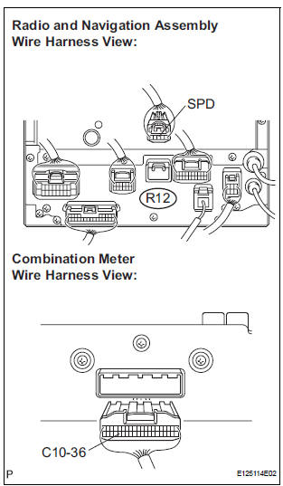
- Disconnect the radio and navigation assembly connector R12 and combination meter connector C10.
- Measure the resistance according to the value(s) in the table below.
Standard resistance
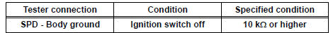
HINT: If the resistance between terminal SPD and body ground is less than 10 kΩ, there may be a short in a wire harness, connector, or an ECU.
REPLACE COMBINATION METER
 Black Screen
INSPECTION PROCEDURE
1 CHECK DISPLAY SETTING
Check that the display is not in "Screen OFF" mode.
OK:
The display setting is not in "Screen OFF" mode.
2 CHECK IMAGE QUALIT ...
 Steering Pad Switch Circuit
DESCRIPTION
This circuit sends an operation signal from the steering pad switch to the
radio receiver.
If there is an open in the circuit, the navigation system cannot be operated
using the st ...
Other materials:
Installation
1. INSTALL ROOF DRIP SIDE FINISH MOULDING
When exchanging the clips
Remove the tape that remains on the mounting
surface of the vehicle body and then clean the
surface with white gasoline.
Using a heat light, heat up the clip installation
surfaces of the vehicle body and moulding.
...
Diagnostic trouble code chart
If a DTC is displayed during the DTC check, check the parts
listed in the table below and proceed to the page given.
HINT:
*1: Comes on MIL (Malfunction Indicator Lamp) light up
*2: "DTC stored" mark means ECM memorizes the
malfunction code if the ECM detects the DTC detection
...
Lumbar support adjuster assembly
INSPECTION
1. INSPECT LUMBAR SUPPORT ADJUSTER ASSEMBLY
Check operation of the lumbar support adjuster
motor.
Check if the lumbar support adjuster moves
smoothly when the battery is connected to the
lumbar support adjuster motor connector
terminal.
OK
If the r ...
