Toyota Sienna Service Manual: Vehicle Speed Signal Circuit between Stereo Component Amplifier and Combination Meter
DESCRIPTION
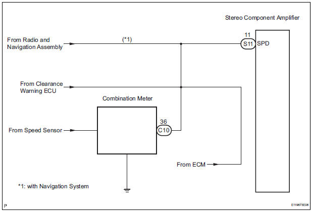
This circuit is necessary for the ASL (Auto Sound Leveliser) built into the stereo component amplifier.
Speed signals are received from the combination meter and used for the ASL.
The ASL function automatically adjusts the sound data in order to enable hearing the clear audio sound even when vehicle noise increases (as vehicle noise increases, the volume is turned up etc.).
HINT:
- A voltage of 12 V or 5 V is output from each ECU and then input to the combination meter. The signal is changed to a pulse signal at the transistor in the combination meter. Each ECU controls the respective system based on the pulse signal.
- If a short occurs in an ECU, all systems in the diagram below will not operate normally.
WIRING DIAGRAM
INSPECTION PROCEDURE
1 OPERATION OF SPEEDOMETER
- Drive the vehicle and check if the function of the speedometer on the combination meter is normal.
OK: Actual vehicle speed and the speed indicated on the speedometer are the same.
HINT: The vehicle speed sensor is functioning normally when the indication on the speedometer is normal
2 INSPECT STEREO COMPONENT AMPLIFIER
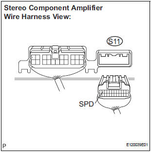
- Disconnect the stereo component amplifier connector S11.
- Measure the voltage.
- Jack up either one of the drive wheels.
- Move the shift lever to the neutral position.
- Turn the ignition switch to the ON position.
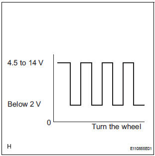
- Measure the voltage between terminal SPD of the stereo component amplifier and body ground when the drive wheels are turned slowly.
OK: Voltage pulses as shown in the illustration.
REPLACE STEREO COMPONENT AMPLIFIER
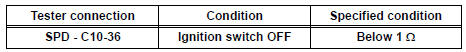
3 CHECK HARNESS AND CONNECTOR (COMBINATION METER - STEREO COMPONENT AMPLIFIER)
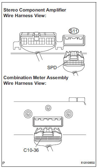
- Disconnect the stereo component amplifier connector S11 and combination meter connector C10.
- Measure the resistance according to the value(s) in the table below.
Standard resistance
4 CHECK HARNESS AND CONNECTOR (COMBINATION METER - STEREO COMPONENT AMPLIFIER)
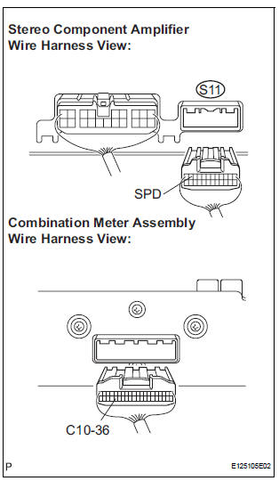
- Disconnect the stereo component amplifier connector S11 and combination meter connector C10.
- Measure the resistance according to the value(s) in the table below.
Standard resistance
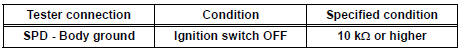
HINT: If the resistance between terminal SPD and body ground is less than 10 kΩ, there may be a short in a wire harness, connector, or an ECU that is connected to the SPD signal wire
REPLACE COMBINATION METER
 Vehicle Speed Signal Circuit between Multi-display and Combination
Meter
Vehicle Speed Signal Circuit between Multi-display and Combination
Meter
DESCRIPTION
This circuit is necessary for the ASL (Auto Sound Leveliser) built into the
radio receiver.
Speed signals are received from the combination meter and used for the ASL.
The ASL fun ...
 Radio Receiver Communication Error
INSPECTION PROCEDURE
1 IDENTIFY THE COMPONENT SHOWN BY THE SUB-CODE
Enter the diagnostic mode
Press the preset switch "3" to change to "Detailed
Information Mode". ...
Other materials:
Open in Rear Curtain Shield Squib LH Circuit
DTC B1636/88 Open in Rear Curtain Shield Squib LH Circuit
DESCRIPTION
The rear curtain shield squib LH circuit consists of the center airbag sensor
assembly and the curtain
shield airbag assembly LH.
The circuit instructs the SRS to deploy when deployment conditions are met.
DTC B1636/88 ...
Reassembly
1. INSTALL REAR DOOR WIRE SUB-ASSEMBLY LH
Install the wire.
NOTICE:
When installing the wire, push the areas where
the clips are installed in order to prevent
damage and deformation.
Install the 2 screws
2. INSTALL REAR DOOR LOCK ASSEMBLY LH
Apply MP grease to the slidin ...
Short to GND in Rear Curtain Shield Squib LH
Circuit
DTC B1637/85 Short to GND in Rear Curtain Shield Squib LH
Circuit
DESCRIPTION
The rear curtain shield squib LH circuit consists of the center airbag sensor
assembly and the curtain
shield airbag assembly LH.
The circuit instructs the SRS to deploy when deployment conditions are met.
DTC ...
