Toyota Sienna Service Manual: Vehicle stability control system
Parts location
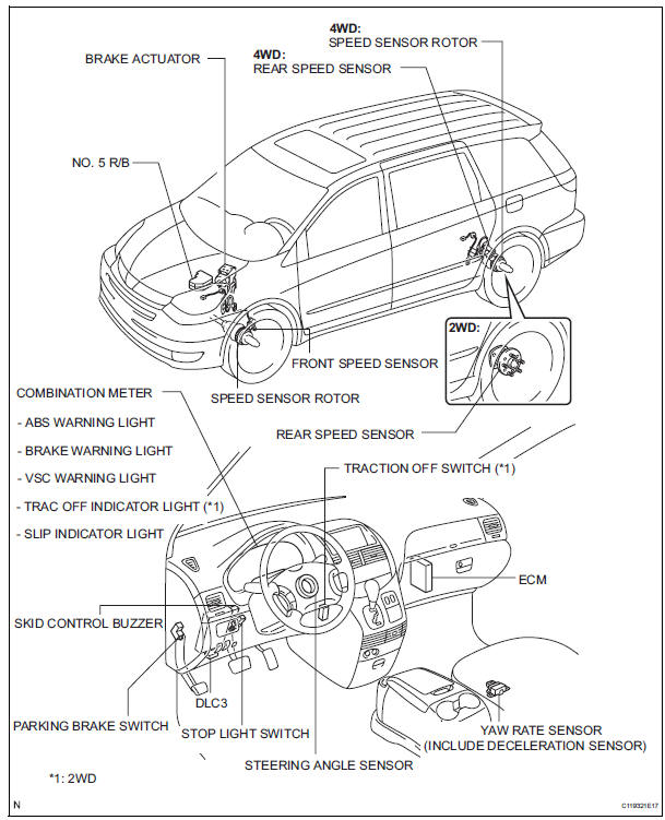
- System description
- How to proceed with troubleshooting
- Calibration
- Test mode procedure
- Terminals of ecu
- Dtc check / clear
- Freeze frame data
- Data list / active test
- Diagnostic trouble code chart
- Problem symptoms table
 TS and CG Terminal Circuit
DESCRIPTION
The Test Mode (signal check) circuit detects trouble in the sensor or switch
signal, which cannot be
detected by the DTC check.
Connecting terminals TS and CG of the DLC3 starts the ...
 System description
1. SYSTEM DESCRIPTION
(a) ABS
(Anti-lock Brake System)
The ABS helps prevent wheels from locking when
the brake is applied firmly or when braking on a
slippery surface.
(b) EBD
(Electronic Brak ...
Other materials:
Removal
1. DISCHARGE FUEL SYSTEM PRESSURE
HINT:
See page FU-1.
2. DISCONNECT CABLE FROM NEGATIVE BATTERY
TERMINAL
3. REMOVE NO. 1 ENGINE UNDER COVER
4. DRAIN ENGINE COOLANT (See page CO-6)
5. REMOVE FRONT WIPER ARM HEAD CAP (See page
WW-4)
6. REMOVE FRONT WIPER ARM RH (See page WW-4)
7. REMOVE FRO ...
Engine Coolant Temperature Circuit
DESCRIPTION
A thermistor is built into the Engine Coolant Temperature (ECT) sensor, of
which the resistance value
varies according to the ECT.
The structure of the sensor and its connection to the ECM are the same as those
of the Intake Air
Temperature (IAT) sensor.
HINT:
When any ...
Installation
1. INSTALL FRONT SEAT ASSEMBLY LH
Place the seat assembly in the cabin.
NOTICE:
Be careful not to damage the body.
Connect the connectors under the seat assembly.
Tighten the 2 bolts on the front side of the seat
assembly.
Torque: 37 N*m (375 kgf*cm, 27 ft.*lb ...
